
Power Considerations for Serial Displays
All of our serial displays operate off common sources of regulated 5Vdc, just like the computer and microcontroller hardware they work with. This page offers hints and techniques for ensuring proper hookup, protecting against power faults, and allowing appropriate power-up timing.
Power Supply Hookup
Most of our displays (BPK, BPI, BPP, and SGX series) use a standardized 5-pin connector for power and serial input. This connector has a reversible layout so that it can be installed without concern for polarity. We offer ready-made wiring harnesses for this connector as well as instructions for fabricating your own.
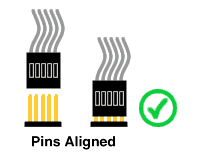
Although using the proper connector goes a long way toward preventing power accidents, you must always ensure that all five pins of the header line up with the five holes of the socket.
 |
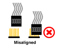 |
| Figure 1. Always align the connector with the header. | |
If the connector and header are misaligned, power polarity will be reversed, possibly damaging the display and the power source. You can reduce the risk somewhat by using only one set of power-carrying conductors (the five-pin layout has two pins for +5V and two pins for ground).
Built-in Power Protection
All of our displays (except ILM-216L) have a 1W, 5.6V Zener diode across the +5V and ground connections (see figure 2 below). If power is connected backwards, the diode will conduct heavily and only about -0.7V will appear across the circuit--a survivable condition. The diode will withstand more than 1A in this condition without damage (although it will get quite hot).
If the supply voltage exceeds ~5.6V, the Zener will also conduct in an effort to maintain ~5.6V across its terminals. However, because power (heat) is the product of current times voltage, the Zener can only withstand less than 200mA in this condition.
When this type of diode fails, it most often welds itself into a short-circuit internally. This is good for our purposes, since the short will often blow a fuse in the power supply, or trigger the supply's current-limiting/thermal shutdown features. If the supply is designed to provide higher current, however, it may blow the diode, or even destroy power traces on the circuit board.
For maximum protection, your power supply must have a fuse, circuit breaker, or current-limiting feature. If your power supply fails, or if you connect power incorrectly, manufacturers (including us) can void their products' warranties.
First Aid for Power Supply Accidents
In spite of your best efforts, somebody has hooked the power up wrong and the display stopped working. What now?
First, find the cause of the problem and correct it. Disconnect the display and use a meter to check the voltage from the power supply. Note and mark the correct polarity, and ensure that the voltage is within say 0.25V of 5.0V.
Check the display power connector and nearby circuit traces for signs of damage (discoloration/charring). Examine the protection diode (D1, fat, glass-bodied diode located near the power connector). If everything looks OK, it probably is (although the diode may have welded short internally; see next step). If the board or any component is burned, return it to us for evaluation/repair. (Use the shipping address at the bottom of this page.)
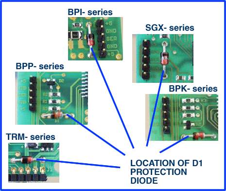 |
| Figure 2. D1 is located close to the power input on all models. |
Next, check the protection diode. If you have a digital multimeter with a diode-check setting, use it. If the diode checks OK, you're ready to reconnect power to the display. If you cannot test the diode, contact Seetron tech support and ask for advice before performing the next step.
If the diode checks bad it has probably welded short internally. This is actually good news, since it is very likely that the display electronics were protected. You have three choices now:
- Void the warranty by clipping the diode out of the circuit. This will probably return the display to operation, but it will be irreparably damaged if another power-supply error or malfunction occurs.
- Void the warranty by replacing the diode yourself with another 5.6V, 1-W Zener.
- Preserve your warranty by shipping the damaged display to us for repair.
If you're confident in your ability as a technician, voiding the warranty to make a quick repair may make more sense than waiting for the shipping turnaround. If you don't have the requisite skills, however, please let us make the repair for you. Our shipping address:
Scott Edwards Electronics Inc.
2160 E. Fry Blvd. Suite C-5 #702
Sierra Vista, AZ 85635
Power-up Timing
Although modern electronic devices seem to snap on instantly when power is applied, microcontroller-equipped devices like our displays require some startup time. Our microcontroller sample programs for driving the displays typically begin with a 1-second delay. Some customers have requested a more precise accounting of startup time. Here it is, by product/series:
| Part # | Time (ms) |
|---|---|
| BPK-000 | 750 |
| BPI-216 | 750 |
| BPP-420L | 110 |
| BPP-440L | 150 |
| GLO-216Y/G | 250 |
| GLO-416Y | 250 |
| SGX-120L | 80 |
| *TRM-425L | 120 |
| *ILM-216L | 150 |
| *Note: These displays have a user-configurable startup delay. The value here is correct when startup delay has been set to 0. | |
These figures are minimums. They were obtained by actual measurements on product samples. Our advice--use the 1-second startup delay unless you have a good reason to do otherwise. If you do shorten the delay, pay close attention to your power supply to ensure that it snaps on crisply. Our displays remain in reset (non-operational state) until power-supply voltage reaches approximately 4.2 to 4.4V. If your supply is slow to reach the operating range, startup time may be longer than the minimum figures listed above.
BPK- and BPI- series Test Mode
BPK- and BPI-series products have a test mode that can be triggered by holding the serial input continuously high throughout startup. From the table above, you can see that that means 750ms after application of power. This condition was chosen as the trigger for test mode precisely because it is not something that would occur on a normally operating serial line. (See serial comms app note)
However, few if any of the serial devices in the world are designed with fastidious standards-compliance in mind. A couple of customers have reported encountering devices that output a high at startup long enough to put connected BPK- or BPI- devices into test mode. Although this startup glitch could be fixed in most cases with a pullup resistor on the input of the offending device's serial line driver, here is an alternative suggestion that works just fine:
Wire a 0.1uF capacitor in series with the SER(ial) input.
This works because the input of BPK- and BPI- devices incorporate a pulldown resistor and diode-clamp circuit. Fast changing signals like the desired serial-input bitstream pass the capacitor, but the relatively long-duration high at startup is effectively blocked.
Naturally, it would be better to fix the output hiccup at the source, but that may not always be possible.