updated March 15, 2011
VFD-420 and VFD-220 are serially interfaced vacuum-fluorescent displays (VFDs). They accept serial input at 2400 or 9600 baud and display text on bright VFD screens. The serial interface understands common control codes (such as linefeeds, carriage returns, tabs, backspace) for easy formatting. Additional instructions position the cursor, set brightness, and store a startup screen in EEPROM.
VFD-420 and -220 are compatible with programs written for Seetron's other advanced serial LCDs (BPP-420, BPP-440, ILM-216, and most text features of SGX- graphics displays).
VFD-420 and VFD-220 version 6.0 are compatible with earlier versions. All previous features are supported, and several new features have been added. Users of previous VFD-420 models should note that the function of configuration switch #1 has changed. It now controls the new EEPROM configuration mode. Its previous function--"old mode" emulation of the LCD Serial Backpack® protocol--is now an EEPROM configuration setting; see Configuring the Display for more information.
Scott Edwards Electronics, Inc. is not responsible for any special, incidental, or consequential damages resulting from any breach of warranty, or under any legal theory, including lost profits, downtime, goodwill, damage to or replacement of equipment or property, and any costs or recovering, reprogramming, or reproducing of data associated with the use of the hardware or software described herein.
Scott Edwards Electronics, Inc. warrants this product against defects in materials and workmanship for a period of 90 days. If you discover a defect, we will, at our option, repair, replace, or refund the purchase price. Return the product with a description of the problem. We will return your product or its replacement via standard shipping. Expedited shipping is available at the customer's expense. Note: Physically abusing the module, removing the daughterboard from the LCD, or attempting to repair or modify the module or the daughterboard, voids this warranty.
All trademarked names mentioned in this document are the property of their respective holders.
Scott Edwards Electronics, Inc.
1939 S. Frontage Road, Suite F
Sierra Vista, AZ 85635 USA
phone: 520-459-4802
fax: 520-459-0623
web: www.seetron.com
email: info@seetron.com
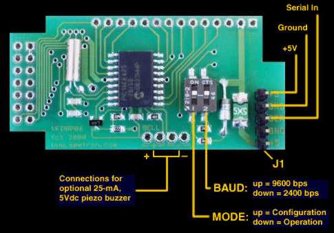
You can demonstrate the display without a serial connection. Move configuration switch 1 to the ON/UP position and connect 5Vdc to J1(see Figure 1). Make sure polarity is correct.
With power connected, the top line of the screen will display "Configuration Mode."
Since configuration mode allows you to change startup settings stored in EEPROM, you should switch to run mode before sending data to the display. Disconnect power, move switch 1 OFF/DOWN, and reconnect power. You may connect RS-232 serial (e.g., from a PC comm port) to the SER pin of J1. See the next section for hookup instructions. Once connected, you can use terminal software to send text and instructions to the display. Configure the software to match the baud rate set by switch 2 (OFF/DOWN=2400 baud; ON/UP=9600 baud).
Figure 1 shows the location and pinout of the display's connector for power and signal. Hookup options include:
 |
| Figure 1. Layout of the interface board. |
| (Note that on the VFD-220 the interface board is upside-down relative to the display.) |
Do not reverse +5V and GND when supplying 5VDC through J1. These connections are protected by a shunt diode on the circuit board. Reversed power will trigger a thermal fuse, which will temporarily disable the unit.
Do not exceed 5.5VDC into the +5V input. Overvoltage may damage the display and/or your power source.
Make sure that your 5Vdc power supply is rated for at least 500mA intermittent and 300mA continuous current. An inadequate power supply will prevent the display from turning on.
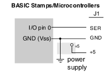
Figure 2 shows typical serial hookups for PCs (and other computers with conventional RS-232 serial ports) and BASIC Stamp® microcontrollers. The power supply must be regulated 5Vdc and rated for at least 500mA intermittent current/300mA continuous.
In the PC hookup drawing, the light-blue lines are "loopback" connections. These are normally not required, but may be needed if the software driving the display expects handshaking. For instance, under MS-DOS, if data is copied to the comm port, DOS expects handshaking. Our software, program examples, and driver DLL do not need these connections.
 |
 |
|
| Figure 2. Serial hookups. | ||
The serial baud rate (2400 or 9600) and operating mode (normal or configuration mode) are controlled by a pair of switches on the interface circuit board. See figure 3.
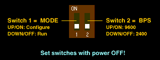 |
| Figure 3. Configuration switch settings. |
Always set these switches with the power OFF. The display reads the switches only at startup.
A piezo buzzer can be connected to pads on the interface board (fig. 1) to beep when the ASCII bell character (ctrl-G, ASCII 07) is received. This buzzer must meet the following requirements:
Suitable buzzers include Radio Shack 273-065, Jameco 76021, and Digi-Key P9948. Note that connecting any load other than a suitable buzzer will void the warranty.
The best way to get acquainted with the display is to connect power and serial data as outlined in the previous sections, boot up a terminal communications program (such as the Serial Sender program on this disk, and type some text and instructions. The text you type in your terminal software will appear on the display. When you set up your terminal program, remember to
With the display powered and connected, anything you type in the terminal program will appear on the LCD. If it does not, check the settings and connection. If text is garbled, chances are that the baud rate is incorrect.
NOTE: This display's control codes are completely compatible with Seetron's other advanced serial displays (e.g., BPP-, ILM- and graphics series). User of these displays should skip ahead and read about new VFD version 6-specific features.
The table below lists the control codes. A separate section lists Escape codes that are used to access the EEPROM and other special functions. To send control codes from most terminal programs, hold down the Control (Ctrl) key and press another key. For example, to send ctrl-L (clear screen), hold down Ctrl and press L. To send control codes from a program, transmit a byte containing the appropriate ASCII value. For example, ctrl-L, the clear-screen instruction, has an ASCII value of 12 (see table). A program would send a byte value of 12 (0C hex or 00001100 binary) to clear the screen.
| ASCII Value | Control Code | ASCII Name | Function |
| 0 | ctrl-@ | NUL | Null; ignored prior to buffer |
| 1 | ctrl-A | SOH | Send cursor home (position 0, upper left corner) |
| 2 | ctrl-B | STX | Begin big characters (-420 only) |
| 3 | ctrl-C | ETX | End big chars (-420 only) or end right-align (both) |
| 4 | ctrl-D | ETO | Turn off cursor |
| 5 | ctrl-E | ENQ | Ignored |
| 6 | ctrl-F | ACK | Turn on block cursor |
| 7 | ctrl-G | BEL | Beep buzzer on J1, pins 7&8 |
| 8 | ctrl-H | BS | Backspace |
| 9 | ctrl-I | HTAB | Tab to next multiple-of-4 column |
| 10 | ctrl-J | LF | Smart linefeed; move down one row |
| 11 | ctrl-K | VTAB | Vertical tab; move up one row |
| 12 | ctrl-L | FF | Formfeed; clear the screen |
| 13 | ctrl-M | CR | Carriage return; move to beginning of next line |
| 14 | ctrl-N | SO | Turn on after power-down |
| 15 | ctrl-O | SI | Power-down the VFD |
| 16 | ctrl-P | DLE | Accept cursor-position data |
| 17 | ctrl-Q | DC1 | Ignored |
| 18 | ctrl-R | DC2 | Accept right-alignment data |
| 19-26 | - | - | All ignored |
| 27 | ctrl-[ | ESC | Escape; begin special instruction |
The serial interface ignores nulls without storing them in its data buffer. Sending a null is the equivalent of a brief time delay. Delay lengths depend on serial speed--at 1200 baud, a null is equal to 8 milliseconds (ms) delay; 2400= 4 ms; 4800= 2ms; and 9600= 1 ms.
Control-A moves the cursor to position 0 (upper left corner) of the display.
[VFD-420 only] Control-B begins big-character mode, in which numbers [0-9], symbols [-.+], and uppercase alpha characters [A..Z] are displayed as four-line-tall characters. The display can only show 4 numbers or letters in this mode. Take care not to update the screen too rapidly in big-character mode; allow 10ms per character, sending nulls if necessary to slow down the updates.
Control-C cancels the big-character mode (VFD-420 only) or right-alignment (both VFD-220 and VFD-420).
Control-D hides the cursor (if cursor is visible).
Control-E is ignored.
Control-F turns on the blinking-block cursor.
Control-G produces a short beep of a piezo buzzer connected between pins 7 and 8 of J1. The beep duration is approximately 100ms.
Backspace, which may also be sent as control-H, causes the cursor to back up one column and print a space, leaving the cursor in that column.
Tab, which may also be sent as control-I, causes the cursor to jump to the next multiple-of-four column position without otherwise affecting the display. For example, if the cursor is at position 0, sending TAB moves it to position 4. Tabs wrap to the next line, or from the last line back to the first line. There are 5 tab stops per line.
Control-J causes the cursor to drop down to the same column of the next display line. If the cursor is on the last line, it will wrap to the first line. The linefeed function is smart because it ignores redundant linefeeds sent immediately after a carriage return.
Control-K causes the cursor to move up to the same column of the preceding display line. If the cursor is on the first line, it will wrap to the last line.
Control-L clears the entire screen and moves the cursor to position 0 (upper left corner) of the display.
Return, which may also be sent as control-M, sends the cursor to the first column of the next line of the display. If return is immediately followed by a linefeed, the linefeed will be ignored.
Control-N turns on the VFD screen after a Control-O power-down.
Control-O puts the VFD into a low-power mode in which the screen is blank, but the interface is ready to receive instructions. Screen contents are not erased by power down and will be restored when the VFD is powered back up using Control-N. In this mode, the display draws less than 20mA, about one-tenth of its normal 200-300mA active current draw.
Control-P puts the display into cursor-positioning mode. In this mode, there are two ways to move the cursor to a particular position on the screen:
Text method: Send the display position as text. For example, from a terminal program, press control-P, then type "13" (just the numbers, not the quotes) followed by a space (to exit the mode). As soon as the space is typed, the cursor will jump to position 13 (14th character of the first line). Note that the space (or other non-numeric character other than null) that terminates position mode is ignored.
One-byte method: Send the display position as a single byte value equal to the position plus 64. For example, from a terminal program, press control-P, then type "A". The cursor will jump to position 1 (second character of the first line) because the ASCII code for A is 65. The serial interface subtracts 64 from the binary value to arrive at the screen position.
With either method the serial interface will accept values larger than the highest valid screen position for the current font. The cursor will simply wrap around until it reaches a valid screen position.
Control-Q erases all four lines of the display (VFD-420) in a vertical column at the current position. On the VFD-220, clears two lines in a vertical column.
Control-R accepts a number from 2 to 9 (as text; ASCII 50-57) representing the width of an area on the screen in which right-aligned text is to be printed. The printing position will back up by that number of characters from its present position. Subsequent text will be stored without printing until one of the following is received:
When one of the conditions listed above is met, the display will print the stored text with right alignment, erasing any leftover text within the specified width.
ASCII codes 19 through 26 are ignored, but do take space in the buffer. Use control-@ (null) if you need a time delay.
Escape tells the serial interface to expect one of the special instructions described in the next section.
Figure 4 shows the display's built-in character set. Some characters are repeated due to the way the firmware rearranges the font layout. This was done to take advantage of some very useful special characters available on this display (partcularly ASCII 160-175; see the figure).
|
|
Figure 4. Character set by ASCII
code. Note: custom characters 0-7 are located at 128-135 in this character set. |
The table below lists the special instructions, which control the display's nonvolatile memory, custom characters, configuration, and other special features. These are called escape sequences because they begin with the escape character (ASCII 27), which distinguishes them from normal text.
| Sequence | Purpose/Effect |
| ESC D n b0 b1 b2 b3 b4 b5 b6 b7 | Define custom character n according to the bit patterns of bytes b0 through b7. Note that n is the printable character for the number, where "0" is ASCII 48 (0x30 hex), "1" is ASCII 49 (0x31 hex) and so on. |
| ESC E n | Load EEPROM data n (0 or 1; screen or custom characters). Note that n is the printable character for the number, where "0" is ASCII 48 (0x30 hex), "1" is ASCII 49 (0x31 hex). |
| ESC W {data} | Write configuration data to EEPROM. Works only with switch #1 in configuration position (ON/UP). See the full description for the contents of {data}. |
| ESC X 0 | Transfer all text from the screen to EEPROM. |
| ESC n | Set the VFD brightness in 25% steps from 0 (25%) to 3 (100%). Note that n is the printable character for the number, where "0" is ASCII 48 (0x30 hex), "1" is ASCII 49 (0x31 hex) and so on. |
| ESC = (style) (width) (value) | Display a horizontal bar graph with the following
specifications:
|
ESC D redefines one of the VFD's custom characters. The VFD has eight custom-character slots, numbered 0-7. These characters are mapped to ASCII codes 128 through 135. At startup, the unit loads these custom characters with shapes needed to support the Ctrl-B Big Characters mode. Using the Define instruction, you can change a custom character. Send Escape (ASCII 27) followed by the letter D (ASCII 68), then the symbol number you wish to define (0 7, ASCII 48 55), followed by eight bytes defining the bitmap.
|
Calculate byte values for this instruction using the Javascript program on the right. Click pixels to toggle them on/off (browser must be version 4 or higher, with Javascript/Jscript turned on). The righthand bit of each row is the least-significant bit of the row byte. HINT: Copy and paste the list of values into your program to save typing. NOTE: Redefining custom characters will garble the Big Character mode, even big characters already on the screen. To restore the original custom characters, use ESC E 1, described below. |
ESC E recalls stored data from EEPROM. ESC E 0 displays the screen stored with ESC X 0. ESC E 1 restores the standard custom-character set needed for the Big-Character mode. Note that "0" and "1" here are the ASCII characters for zero and one; ASCII 48 and 49 (hex 0x30 and 0x31) respectively.
ESC W accepts 8 bytes of configuration data and writes it to the EEPROM. This instruction works only when switch 1 on the interface board is in the ON/UP position at startup. When this switch is correctly set, the screen will display Configuration Mode when power is applied.
The easiest way to perform ESC W configuration is by using the free configuration program, described in the next section. However, you may also configure the display with any computer capable of sending the appropriate data serially.
Note that all of the configuration bytes default to 128 (bit 7 set to 1). This is because the display ignores nulls (ASCII 0).
Timing: Allow at least 20ms after sending configuration data before sending anything else. This is the time required for the display to write its internal EEPROM.
Here is a byte-by-byte description of the configuration data:
| Byte # | Function |
| b0 | Initial Brightness, 128 + brightness setting (0-3):
|
| b1 | Startup Screen, 128 + ON (1) or OFF (0):
|
| b2 | Power up time (in 0.5-second units): Valid inputs are 1-120; power-up time of 0 is represented by any value greater than 120. |
| b3 | Mode settings, 128 + mode options. Add the
following option values, plus 128, to arrive at the ASCII code for
b3:
|
| b4 - b7 | Reserved for future use; send ASCII 128 for all. |
ESC X 0 (where "0" is ASCII 48, zero) copies the current screen contents to EEPROM. This completely overwrites any previously stored screen. The screen may be recalled using ESC E 0 (above). The screen will also display at startup if the unit is configured to do so (ESC W).
Example: to store the current text screen to EEPROM, send ESC X 0 (three bytes, values 27 88 48).
Note that ESC X 0 will not work if the EEPROM has been write protected (see ESC W). Also note that if the screen uses custom characters (ASCII 128-135), the same custom-character patterns must be in effect when it is recalled.
Timing: Allow at least 200ms after the transfer instruction before sending anything else. This is the time required for the display to write its internal EEPROM.
ESC n sets the VFD brightness from 25% to 100% in units of 25%. The value of n is specified by the printable numbers "0" to "3" (ASCII 48-50; hex 0x30-0x32).
Example: to set 50% brightness, send ESC 1 (two bytes, values 27 49)
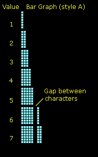
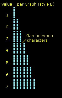
ESC = draws a horizontal bar graph from the current cursor location, then returns the cursor to that location. You must specify the style, width (in characters) and value (in units of 3 or 5 bars/character) as follows:
 |
 |
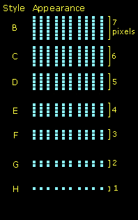 |
| Figure 5. Bar-graph styles. | ||
Example 1: Cursor is in the home position (upper-left corner) To create a bar graph with a 4-pixel bar, spanning the whole 20-character line and depicting a value of 38 (out of 60), send ESC = E 20 SPACEBAR 38 SPACEBAR (where SPACEBAR indicates the space character, ASCII 32. The ASCII codes for this would be: 27 61 45 50 48 32 51 56 32. This sequence could be typed from the keyboard with a terminal program.
Example 2: Same as Example 1, but sent by using single bytes (and no spaces) for the width and value parameters. To represent these numbers with single bytes, add 64. So the sequence would be ESC = E T f or ASCII codes 27 61 45 84 102.
Custom Characters and Bar Graphs: Bar-graph styles "B" through "H" (and "b" through "h") use custom characters (ASCII 128-135). They automatically redefine custom character to draw the graph. This will override any custom characters you have defined with ESC D, and will garble any ctrl-B big characters (big characters available in VFD-420 only).
To restore the default custom-character set (for big characters), use ESC E 1. To avoid custom-character problems, use the "A" or "a" bar-graph style.
Bar Graph Timing: Bar graphs can take up to approximately 2ms to generate. At 9600 bps, new data can arrive in 1ms. If bar graphs are updated rapidly, they may overflow the buffer. If this occurs, insert a null (ASCII 0) after each update for a small delay.
The display can be configured using the instructions described above, but this disk includes Windows software to configure the display. You can pick and download settings to the display through a PC serial port.
The VFD configuration software is included on this disk. It requires no installation; just double-click to run. To remove it, drag it to the Trash. It makes no changes to the system.
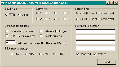 |
Figure 6. Point and click to configure your VFD. |
To use the program, connect the display to the PC comm port using the hookup shown in Figure 2. Set switch #1 ON/UP and connect power. When display powers up in configuration mode, it displays the message "Configuration Mode" on the screen.
Run the configuration program by double-clicking its icon. Each of the configuration options is described below.
Set the baud rate to match the display's baud rate (switch #2):
Select the comm port to which the display is connected.
Set the screen type to match your display; 4x20 for VFD-420 or 2x20 for VFD-220.
Show startup screen
![]() Display EEPROM text screen
when first powered up.
Display EEPROM text screen
when first powered up.
![]() Leave screen blank
when first powered up.
Leave screen blank
when first powered up.
EEPROM write protect
![]() Prevent EEPROM text screen
from being changed when the display is not in configuration
mode.
Prevent EEPROM text screen
from being changed when the display is not in configuration
mode.
![]() Allow the EEPROM
text screen to be rewritten at any time.
Allow the EEPROM
text screen to be rewritten at any time.
Old mode (BPK style)
![]() Force the VFD to emulate the
instruction mode of Seetron BPK- or BPI- series products. Use this
option if you are replacing an older VFD-420 (v4.0 or earlier) that
had configuration switch #1 in the ON/UP position. Do not
use in normal applications; see old mode
in Design Notes and Specifications.
Force the VFD to emulate the
instruction mode of Seetron BPK- or BPI- series products. Use this
option if you are replacing an older VFD-420 (v4.0 or earlier) that
had configuration switch #1 in the ON/UP position. Do not
use in normal applications; see old mode
in Design Notes and Specifications.
![]() Allow normal
operation as described in this manual.
Allow normal
operation as described in this manual.
Disable auto dim
![]() Maintain constant VFD
brightness.
Maintain constant VFD
brightness.
![]() Automatically dim
VFD 25% every 100 seconds without serial input (see auto-dim in Design Notes and
Specifications).
Automatically dim
VFD 25% every 100 seconds without serial input (see auto-dim in Design Notes and
Specifications).
Power-up delay
![]() Enter a power-up delay time in
units of one-half second from 0 to 120. During this delay, serial
input is ignored. This feature is useful if your computer emits
garbage characters through the serial port at startup. Otherwise,
set to 0.
Enter a power-up delay time in
units of one-half second from 0 to 120. During this delay, serial
input is ignored. This feature is useful if your computer emits
garbage characters through the serial port at startup. Otherwise,
set to 0.
Brightness at startup
Select desired display brightness from
![]() (dim) to
(dim) to ![]() (full brightness). During
operation, brightness can be adjusted using ESC n.
(full brightness). During
operation, brightness can be adjusted using ESC n.
Screen contents
![]() Enter text for your EEPROM text
screen in these lines. Two lines will be disabled if you chose 2x20
in Screen Type.
Enter text for your EEPROM text
screen in these lines. Two lines will be disabled if you chose 2x20
in Screen Type.
Send text
![]() Download the text entered
above to the display screen.
Download the text entered
above to the display screen.
![]() Do not download text
to the display; send only configuration options when Send button is
pressed.
Do not download text
to the display; send only configuration options when Send button is
pressed.
Store to EE
![]() Store the downloaded text into
EEPROM. This option is disabled if you unchecked "send text."
Store the downloaded text into
EEPROM. This option is disabled if you unchecked "send text."
![]() Download the text to
the screen, but do not store it in EEPROM.
Download the text to
the screen, but do not store it in EEPROM.
Click the Send button to download your
configuration choices to the display. When you are done configuring
display(s), you may quit the program by clicking the close
(![]() ) button.
) button.
VFD-420 and -220 are designed to speed prototyping and enable the creation of bench-top instruments requiring a serially driven text display. They are not meant for direct use by non-technical users or for incorporation into mass-produced consumer equipment. They have not been tested to EMC/EMI/ESD standards. (The same is true of most single-board computers and other subassemblies whose specs do not specifically include compliance data.) It is up to the purchaser to determine whether the unit is suitable for the intended use.
This unit is designed and manufactured to high standards of quality. This notice is simply intended to head off invalid assumptions that might affect decisions about using it in consumer products.
The following data is preliminary and subject to change without notice. The VFD unit consists of two subassemblies--a VFD module, and a custom serial controller. Where the ratings of these two devices vary, the more conservative rating is shown in the table.
| Parameter | min | max | typical | unit |
| Operating temperature range | -20 | +70 | - | °C |
| -4 | +158 | - | °F | |
| Storage temperature range | -40 | +85 | - | °C |
| -40 | +185 | - | °F | |
| Supply voltage to J1 ("5V") | 4.75 | 5.25 | 5.00 | Vdc |
| Current draw, startup surge | - | 500 | - | mA |
| Current draw, operating | - | 350 | 300 | mA |
| Processor clock speed | - | - | 16 | MHz |
| *Note: Current draw varies with the number of lit pixels on the VFD screen. | ||||
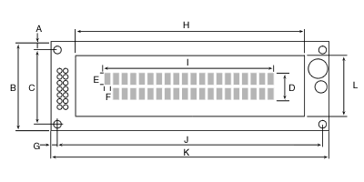
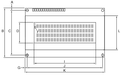
| A | y offset edge to hole center (top & bottom) | 4.00 |
| B | y pcb height | 37.00 |
| C | y hole spacing | 29.00 |
| D | y display area | 11.50 |
| E | y character size | 4.70 |
| F | x character size | 2.40 |
| G | x offset pcb edge to hole center | 4.00 |
| H | x screen frame (glass envelope) | 95.30 |
| I | x display area | 70.80 |
| J | x hole spacing | 108.00 |
| K | x pcb width | 116.00 |
| L | y screen frame (glass envelope) | 25.35 |
| - | mounting hardware (screw size/thread) | 4-40 |
|
||
| A | y offset edge to hole center (top & bottom) | 2.50 |
| B | y pcb height | 60.00 |
| C | y hole spacing (inside pair) | 55.00 |
| D | y display area | 20.90 |
| E | y character size | 4.70 |
| F | x character size | 2.40 |
| G | x offset pcb edge to hole center | 2.50 |
| H | x screen frame (glass envelope) | 96.00 |
| I | x display area | 70.80 |
| J | x hole spacing | 93.00 |
| K | x pcb width | 98.00 |
| L | y frame height (glass envelope) | 35.00 |
| - | mounting hardware (screw size/thread) | 2-56 |
| - | frame depth | 14.00 |
|
||
VFDs can be damaged by careless handling. The manufacturer offers these suggestions for safe handling of VFDs:
One of the configuration options is Old Mode, which makes the display emulate the LCD Serial Backpack®, BPI-series displays, and older VFD-420s with switch #1 set up/ON. In Old Mode, the display does not interpret control characters like Ctrl-L for clear screen. Instead, it recognizes one special character, ASCII 254 (0xFE hex), as an instruction prefix. The byte immediately following ASCII 254 will be passed to the VFD as an instruction code rather than a printable character.
This mode is for backward compatibility; we do not recommend it for new users.
The pixels of the VFD screen lose brightness gradually in proportion to their ON time. Leaving a fixed message on the VFD for long periods of time causes burn-in , making overused pixels noticeably dimmer than the rest.
When you write programs to drive the VFD, avoid burn-in. Change screen text periodically to spread the wear more evenly.
VFD-220 and -420 (v5 and higher) have a screen saver to combat burn-in. If no serial input is received for 100 consecutive seconds, the display automatically dims by 25%. Assuming that it starts at 100% brightness, after 5 minutes of inactivity (300 seconds) the display drops to 25% brightness. Auto-dimming will not turn the display completely off.
Any serial data received after auto-dimming begins will cause the display to return to its previous brightness level (default is 100%, but can be overridden by ESC n brightness commands sent by your program).
To disable auto-dimming, send data at intervals of less than 100 seconds. Any data--even 'ignored' codes --will prevent auto-dimming. The only excepttion is ASCII 0 (null), which is not buffered.
You can also disable auto-dimming in the display's EEPROM configuration; see the configuration software writeup.
Any computer/programming language that can communicate serially at 2400 or 9600 baud can drive these displays. These examples are in BASIC, chosen because of its popularity and readability. Programs written for our BPP-, ILM-, and TRM-series LCD products will work with VFD- series displays; please see our web site for examples.
A Windows® program example using Visual BASIC® is available from our web site along with a free serial-send DLL.
Our free serial-sender program for Windows® is a simple way to send test data to a comm port. It's ideal for demonstrating and understanding the display's capabilities.
To use Serial Sender, set the baud rate to match your display (switch 2; UP/ON=9600, DOWN/OFF=2400) and select the comm port to which the display is connected.
Type text into the box and press Send. The text is sent to the display using the selected baud rate and comm port.
To send a control character, enclose the corresponding letter in angle brackets like so: <L> (ctrl-L, which the VFD interprets as clear-screen). The program also understands the standard ASCII names for control characters, such as ESC for the Escape character that begins special instructions: <ESC>. For a complete list, go online and see the Serial Sender DLL application note.
Finally, you can use ASCII values to specify the character to send, as in <12> (ASCII 12; same as ctrl-L for clear-screen). Note that you can place multiple ASCII values and codes in one set of brackets by separating them with commas: <12,6> (ASCII 12 clear screen, then ASCII 6 cursor on).
This manual lists the VFD's instructions by control character and/or ASCII value, so it's easy to use Serial Sender for demonstration purposes. Here are a few example that you can copy and paste from this document into Serial Sender's text box:
| Copy and Paste into Serial Sender (triple-click in box to automatically select for copying) | ..to Produce this Effect |
|---|---|
| <L>Hello World! | Clear the screen and print "Hello World!" |
| <12>Hello World! | same, with ASCII values |
| <L,B>WOW<C> | (VFD-420 only!) Clear screen, enter big-character mode, print "WOW", exit big-char mode |
| <12,2>WOW<3> | same, with ASCII values |
| <L,ESC>=A20.77. | Clear screen, send escape code for bar graph 20 characters wide, set to a value of 77 |
| <12,27>=A20.77. | same, with ASCII values |
| <12,27,61,65,84,141> | same, using byte values for all |
| <L>Not too bright..<ESC>0 | Clear screen, print message, set to lowest brightness |
| <12>Not too bright..<27,48> | same, with ASCII values |
| <L>Dazzling!<ESC>3 | Clear screen, print message, set to highest brightness |
| <12>Dazzling!<27,51> | same, with ASCII values |
| <L,TAB,TAB,TAB,R>5123.75 | Clear screen, tab over 12 spaces, set right-align (ctrl-R) in 5-char space, print 123.75 |
| <12,9,9,9,18,53>123.75 | same, with ASCII values |
Summary: This program just prints a phrase on the display. It demonstrates clearing the screen and printing text.
Power:
Power (Board of Education or other proto board with built-in 500+mA 5Vdc supply):
Configuration: Set configuration switch #2 up/ON for 9600 bps.
' Program: VFDHELLO ("Hello World" demo for VFD/BS2)
' This program shows how to clear the screen
' and print text to the VFD.

' ===========Define Instruction(s)==========
CLRVFD  con     12      ' Clear screen.

' Uncomment (remove the ' mark from) the appropriate
' baud rate to match VFD baud setting. Comment
' out the others.
BAUD    con     $4054   ' 9600 baud, BS2.
'BAUD   con     $418D   ' 2400 baud, BS2.
'BAUD   con     $40F1   ' 9600 baud, BS2-SX.
'BAUD   con     $43FD   ' 2400 baud, BS2-SX.

' ===========Begin demonstration=======
pause 1000                              ' Wait a sec.
serout 0,BAUD,[CLRVFD,"Hello World!"]   ' Clear, print text.
STOP    ' Done. End program
Summary: This program enables you to configure the VFD EEPROM using the BS2
Power: As listed above.
Configuration: Set both configuration switches up/ON for config mode and 9600 bps.
' Program: VFDCFG (Configuring VFD with BS2)
' This program shows how to write configuration
' data to VFD-420 or VFD-220 using the BS2.
' The VFD must be in configuration mode
' (switch 1 on interface ON) for this to
' work.

' ===========Define Instruction(s)==========
CLRVFD  con     12      ' Clear screen.
ESC     con     27      ' The Escape character.
WIDTH   con     20      ' Screen width (do not change)

' Uncomment (remove the ' mark from) the appropriate
' baud rate to match VFD baud setting. Comment
' out the others. VFD baud is set by switch 2
' on the interface board; ON=9600, OFF=2400.
BAUD    con     $4054   ' 9600 baud, BS2.
'BAUD   con     $418D   ' 2400 baud, BS2.
'BAUD   con     $40F1   ' 9600 baud, BS2-SX.
'BAUD   con     $43FD   ' 2400 baud, BS2-SX.

' =========== VFD configuration ==========
' These constants control various VFD startup
' settings. Assign them to the appropropriate
' variables (marked by <--) to create your
' custom configuration.

' ==Settings for 'brite'
BRIGHT25        con     128     ' 25% brightness
BRIGHT50        con     129     ' 50% brightness
BRIGHT75        con     130     ' 75% brightness
BRIGHT100       con     131     ' 100% brightness
brite   var     byte    ' Brightness variable
  brite = BRIGHT100     '<-- Set brightness (BRIGHT25-BRIGHT100)

' ==Settings for 'startScreen'
BLANK   con     128     ' Start up with screen blank
SHOW    con     129     ' Start up with EEPROM-stored screen
startScreen     var     byte    ' Start screen variable
  startScreen = SHOW    '<--Set start screen (BLANK or SHOW)

' ==Settings for 'startDelay'
' Start delays (period after power-on during
' which the display ignores serial input) can
' range from 1 to 120 in units of 0.5 second.
' To get a 0-second delay, set this value to
' greater than 120.
ZERO    con     128     ' Start up with screen blank
startDelay      var     byte    ' Start delay variable
  startDelay =  ZERO    '<--Set start delay (1-120, or ZERO)

' ==Options for 'mode'
' Add up the desired options and assign them
' to the variable 'mode'
OPTIONS         con     128     ' Add options to this value
NORMAL          con     0       ' Normal operation
OLDMODE         con     1       ' Emulate BPK, BPI-series displays
WRITEOK         con     0       ' Allow EEPROM writes
WRITENO         con     2       ' Prevent EEPROM writes
DIMSOK          con     0       ' Allow auto-dimming
DIMSNO          con     4       ' Prevent auto-dimming
mode    var     byte            ' Mode variable
  mode = OPTIONS+NORMAL+WRITEOK+DIMSOK '<--Set options

' ==Reserved values
' Unused configuration bytes all set to 128.
UNUSED  con     128     ' Default value for unused bytes

' ==Number of lines for EEPROM screen
' Set this variable to the number of lines (2 for VFD-220
' or 4 for VFD-420) on your display. If you don't want
' to load an EEPROM screen, set this variable to 0.
lines   var     nib
  lines = 4     '<--Set # of lines (0,2,4)

' ==EEPROM screen text
' Text to be stored in EEPROM for startup screen or
' instant recall with ESC E 0 instruction.
' If no startup or EEPROM screen is desired, set
' the variable "lines" above to 0.
LINE1   DATA    "Line 1 text"   ,0      '<--Change text in ""s
LINE2   DATA    "Line 2 text"   ,0      ' as desired for
LINE3   DATA    "Line 3 text"   ,0      ' corresponding
LINE4   DATA    "Line 4 text"   ,0      ' lines of display.
i       var     word            ' String index.
char    var     byte            ' String character.
strAdr  var     word            ' Starting address of string

' ===========Begin configuration=======
pause 1000                              ' Wait a sec.
serout 0,BAUD,[ESC,"W",brite,startScreen,startDelay,mode,REP UNUSED \4]
pause 500
serout 0,BAUD,[CLRVFD,"Configuration done."]
pause 1000

SetScreen:
  if lines = 0 then screenDone
   serout 0,BAUD,[CLRVFD]
   strAdr=LINE1
   GOSUB PrintToWidth
   strAdr=LINE2
   GOSUB PrintToWidth
  if lines = 2 then transferToEE
   strAdr=LINE3
   GOSUB PrintToWidth
   strAdr=LINE4
   GOSUB PrintToWidth
transferToEE:
  serout 0,BAUD,[ESC,"X0"]      ' Transfer to EEPROM
screenDone:
  stop

' PrintToWidth takes text saved as EEPROM data
' and terminated with a 0 value, and prints it
' serially to the width specified by the constant
' WIDTH. If the string is shorter than WIDTH, it
' is padded with spaces; if wider, it is shortened.
' The string to print is specified by an EEPROM
' data address in the variable strAdr.
PrintToWidth:
  i = 0                         ' Clear length count.
readNext:
  read strAdr,char              ' Get the character
  if char = 0 then endString    ' 0 marks end of string
  serout 0,BAUD,[char]          ' Print the character
  strAdr=strAdr+1               ' Point to next character
  i=i+1
  if i=WIDTH then doReturn
goto readNext
endString:
  serout 0,BAUD,[REP " " \(WIDTH-i)]
doReturn:
  return