updated April 04, 2000
Description
The TRM-425 Serial LCD Terminal communicates serially at 1200 to 9600 bits per second (bps), displays text on a 4-line by 20-character screen, and can report keypresses from a matrix keypad with up to 16 keys.
Common terminal/printer control codes (such as linefeeds, carriage returns, tabs, backspace, formfeeds) allow easy formatting of the display. Additional instructions permit cursor positioning, backlight control, custom configuration, and storage of up to 95 screens and 8 sets of custom characters in nonvolatile EEPROM.
TRM-425 is compatible with programs written for Seetron's other advanced serial LCDs (BPP-420, BPP-440, ILM-216, and most text features of SGX- and BGX- graphics displays).
Table of Contents
Scott Edwards Electronics, Inc. is not responsible for any special, incidental, or consequential damages resulting from any breach of warranty, or under any legal theory, including lost profits, downtime, goodwill, damage to or replacement of equipment or property, and any costs or recovering, reprogramming, or reproducing of data associated with the use of the hardware or software described herein.
Scott Edwards Electronics, Inc. warrants this product against defects in materials and workmanship for a period of 90 days. If you discover a defect, we will, at our option, repair, replace, or refund the purchase price. Return the product with a description of the problem. We will return your product or its replacement via standard shipping. Expedited shipping is available at the customer's expense. Note: Physically abusing the module, removing the daughterboard from the LCD, or attempting to repair or modify the module or the daughterboard, voids this warranty.
Trademarks
Windows® is a registered trademark of Microsoft, Inc. Other trademarked names that may be mentioned in the body of this document are the property of their respective holders.
Scott Edwards Electronics, Inc.
1939 S. Frontage Road, Suite F
Sierra Vista, AZ 85635 USA
phone: 520-459-4802
fax: 520-459-0623
web: www.seetron.com
email: info@seetron.com
You can demonstrate the TRM-425 without a serial connection. Install a jumper at CFG (configuration) and connect a 9V battery (or 7 to 10Vdc source) to pins 1 and 2 of J1 on the TRM circuit board (see Figure 1). Make sure polarity is correct.
With power connected, the screen will display the version number and a list of settings stored in non-volatile memory (EEPROM).
Since configuration mode allows you to change startup settings stored in EEPROM, you should remove the CFG jumper before sending serial data to the TRM-425. Disconnect power, pull the jumper, and reconnect power. You may connect RS-232 serial (e.g., from a PC comm port) to J3 at the upper-left portion of the interface board. See the next section for hookup instructions. Once connected, you can use terminal software to send text and instructions to the display. Configure the software to match the baud rate shown on the configuration screen; 9600 baud is the default.
Figure 1 shows the locations of the TRM's connectors for power, signal, etc.
The simplest power hookup is the included 9V battery snap. Connect it to pins 1 and 2 of J1 as shown in the figure. You may substitute an ac adapter (7 to 10Vdc) for the battery. You may also connect regulated 5VDC power to J1 via pin 1 (GND) and pin 3 (+5V). Make sure that your power supply is regulated to 5Vdc �0.25V and is capable of supplying up to 75 mA. Don't connect power to both +9V and +5V inputs at the same time.
 |
Figure 1. Locations of connectors on TRM pcb,
connecting 9V snap to J1 (below).
|
Pinouts of Connectors J2 and J1
J2 (keypad) | J1 (power/IO) |
| Pin |
Function |
Pin |
Function |
| 1 |
row 4 |
1 |
GND |
| 2 |
row 3 |
2 |
+9V in (1) |
| 3 |
row 2 |
3 |
+5V in (1) |
| 4 |
row 1 |
4 |
TTL Serial in (2) |
| 5 |
col 4 |
5 |
TTL Serial out (2) |
| 6 |
col 3 |
6 |
Key strobe I/O |
| 7 |
col 2 |
7 |
Buzzer + |
| 8 |
col 1 |
8 |
Buzzer - |
NOTES:
(1) Connect either unregulated +9V to pin 2 or regulated +5V to pin 3, but not both.
(2) Non-inverted TTL (+5V) serial only. Connect RS-232 (+/-10V serial) to J3 only.
|
|
|
 Power Supply Cautions
Do not reverse +5V and GND when supplying 5VDC through J1. These connections are protected by a shunt diode on the circuit board. A reversed connection will look like a short-circuit to your power supply and may damage it. A sufficiently powerful supply connected backwards may destroy the diode and the display.
Do not exceed 5.5VDC into the +5V input. Overvoltage may damage the TRM and/or your power source.
Do not connect anything to +9V (J1 pin 2) when supplying 5VDC through J1 pin 3.
Do not tap into the TRM's 5-volt supply to power other devices. When the backlight is turned on, the regulator is near its maximum continuous current rating.
There are two places to connect serial I/O to the TRM; one for PCs and other RS-232 devices, the other for BASIC Stamps®, microcontrollers, UARTS, and other logic-level serial devices.
PCs and RS-232 Hookup
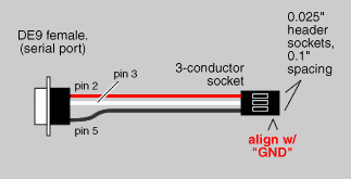
Connect RS-232 serial I/O to the TRM via J3, the three-pin connector at the upper left of the interface board (see figure 1 above). A PC/RS-232-compatible cable is available separately as part number TRM-CBL. When using this cable, make sure that the black wire aligns with the pin marked GND. Figure 2 below shows how TRM-CBL is wired.
Figure 2. Wiring of TRM-CBL for PC serial hookup.
TIP: If you are using a single-board computer and are not sure whether the serial I/O is RS-232 or not, here's how to check. With the port enabled but not sending any data (idle) check the voltage on the transmit-data line. If it is negative (e.g. -10V), then the port is RS-232. If the idle voltage is positive (+2.5V or greater) then it's non-inverted TTL and should be connected as described in the next section.
Non-Inverted, Logic-Level Serial (Stamps®, Direct UART Connections)
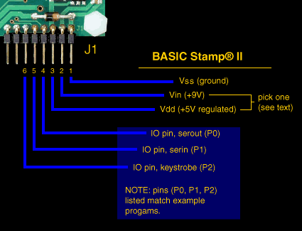
Figure 3 shows how to connect BASIC Stamps®. The BASIC Stamp® can use any I/O pin for serial input or output, so you may change the pin assignments for your application. The pins used in the figure match the example programs presented in this manual. NOTE: Any unused feature can be left unconnected. For instance, if you don't have a keypad, you don't need to connect J1/pin 5 (TRM serial output) to the Stamp.
For other microcontrollers whose serial I/O is logic-level (5V) rather than RS-232 (+/- 10V), the same connection scheme applies. The pin marked "serout" is the non-inverted, logic-level serial output of your micro (e.g., data output of a UART); "serin" is serial input to the UART or micro; and "keystrobe" should be a general-purpose IO pin.
Figure 3. Connecting TRM to BASIC Stamp® II.
If your Stamp or other micro has a regulated 5V supply with at least 70mA of spare current capability, we suggest connecting that +5V supply to pin 3. Otherwise, connect unregulated +7V to +10V to pin 2.
J2 is the keypad connector. It is arranged to match the connector layout of popular 4x4 matrix keypads. Click here for more information on keypads, connectors, etc.
Even if the wiring layout of your keypad does not match that of the TRM, you will probably be able to adjust the configuration of the TRM to accommodate it. For example, if the sets of row and column connections are reversed with respect to TRM J2, just keep this in mind when configuring the TRM key codes.
For more on keypad configuration, see Using the Keypad Capabilities.
A piezo buzzer can be connected to J1 (pins 7 and 8; see figure 1) to beep when the ASCII bell character is received, or (optionally) when a keypress is detected. This buzzer must meet the following requirements:
- Built-in driver (oscillator)
- 5Vdc at 25mA (max)
Suitable buzzers include Radio Shack 273-065, Jameco 76021, and Digi-Key P9948. Note that connecting any load other than a suitable buzzer will void the warranty.
A contrast-control pot, located under J3 on the TRM board, sets the initial contrast of the LCD display. Contrast is factory set, and should not require adjustment. A temperature-compensation circuit maintains contrast throughout the operating range of 0° to 50°C (32° to 122°F). You may tweak the contrast setting by turning this control slightly while viewing the display.
The best way to get acquainted with the TRM is to connect power and serial data as outlined in the previous sections, boot up a terminal communications program (such as the Serial Sender program available free from www.seetron.com, and type some text and instructions. The text you type in your terminal software will appear on the display. When you set up your terminal program, remember to
- Set the program and the display for the same baud rate.
- Configure the program for no parity, 8 data bits, 1 stop bit.
- Turn off hardware handshaking.
- Set the program for the com port to which the display is connected.
- To see your typing on the PC monitor, set the program for "half duplex."
With the TRM powered and connected, anything you type in the terminal program will appear on the LCD. If it does not, check the settings and connection. If text is garbled, chances are that the baud rate is incorrect. You can double-check the TRM's baud rate setting by powering it down, installing the CFG jumper and powering back up. The CFG screen will display the baud-rate setting.
NOTE: TRM's control codes are completely compatible with Seetron's other advanced serial displays (e.g., BPP-, ILM- and graphics series). User of these displays should skip ahead and read about new TRM-specific features.
The table below lists the control codes. A separate section lists Escape codes that are used to access the EEPROM and other special functions. To send control codes from most terminal programs, hold down the Control (Ctrl) key and press another key. For example, to send ctrl-L (clear screen), hold down Ctrl and press L. To send control codes from a program, transmit a byte containing the appropriate ASCII value. For example, ctrl-L, the clear-screen instruction, has an ASCII value of 12 (see table). A program would send a byte value of 12 (0C hex or 00001100 binary) to clear the screen.
| ASCII Value |
Control Code |
ASCII Name |
Function |
| 0 |
ctrl-@ |
NUL |
Null; ignored prior to buffer |
| 1 |
ctrl-A |
SOH |
Send cursor home (position 0, upper left corner) |
| 2 |
ctrl-B |
STX |
Begin big characters |
| 3 |
ctrl-C |
ETX |
End big characters |
| 4 |
ctrl-D |
ETO |
Turn off cursor |
| 5 |
ctrl-E |
ENQ |
Turn on underline cursor |
| 6 |
ctrl-F |
ACK |
Turn on block cursor |
| 7 |
ctrl-G |
BEL |
Beep buzzer on J1, pins 7&8 |
| 8 |
ctrl-H |
BS |
Backspace |
| 9 |
ctrl-I |
HTAB |
Tab to next multiple-of-4 column |
| 10 |
ctrl-J |
LF |
Smart linefeed; move down one row |
| 11 |
ctrl-K |
VTAB |
Vertical tab; move up one row |
| 12 |
ctrl-L |
FF |
Formfeed; clear the screen |
| 13 |
ctrl-M |
CR |
Carriage return; move to beginning of next line |
| 14 |
ctrl-N |
SO |
Turn backlight on |
| 15 |
ctrl-O |
SI |
Turn backlight off |
| 16 |
ctrl-P |
DLE |
Accept cursor-position data |
| 17 |
ctrl-Q |
DC1 |
Ignored |
| 18 |
ctrl-R |
DC2 |
Accept right-alignment data |
| 19-26 |
- |
- |
All ignored |
| 27 |
ctrl-[ |
ESC |
Escape; begin special instruction |
Null ASCII 0 (Control-@)
TRM-425 ignores nulls without storing them in its data buffer. Sending a null is the equivalent of a brief time delay. Delay lengths depend on serial speed--at 1200 baud, a null is equal to 8 milliseconds (ms) delay; 2400= 4 ms; 4800= 2ms; and 9600= 1 ms.
Control-A moves the cursor to position 0 (upper left corner) of the display.
Big-character Mode ASCII 2 (Control-B)
Control-B begins big-character mode, in which numbers [0-9], symbols [-.+], and uppercase alpha characters [A..Z] are displayed as four-line-tall characters. The display can only show 4 numbers or letters in this mode. Take care not to update the screen too rapidly in big-character mode; allow 10ms per character, sending nulls if necessary to slow down the updates. (As a practical matter, the LCD cannot update much faster than 10x/second, so sending big characters rapidly just produces a blur on the screen anyway.)
Cancel Big-character Mode ASCII 3 (Control-C)
Control-C cancels the big-character mode begun with ctrl-B.
Control-D hides the cursor (if cursor is visible).
Underline Cursor ASCII 5 (Control-E)
Control-E turns on the underline cursor.
Block Cursor ASCII 6 (Control-F)
Control-F turns on the blinking-block cursor.
Control-G produces a short beep of a piezo buzzer connected between pins 7 and 8 of J1. The beep duration can be set from 0 to 127ms during configuration.
Backspace ASCII 8 (Control-H or Backspace key)
Backspace, which may also be sent as control-H, causes the cursor to back up one column and print a space, leaving the cursor in that column.
Horizontal Tab ASCII 9 (Control-I or Tab key)
Tab, which may also be sent as control-I, causes the cursor to jump to the next multiple-of-four column position without otherwise affecting the display. For example, if the cursor is at position 0, sending TAB moves it to position 4. Tabs wrap to the next line, or from the last line back to the first line. There are 5 tab stops per line.
Smart Linefeed ASCII 10 (Control-J)
Control-J causes the cursor to drop down to the same column of the next display line. If the cursor is on the last line, it will wrap to the first line. The linefeed function is smart because it ignores redundant linefeeds sent immediately after a carriage return.
Control-K causes the cursor to move up to the same column of the preceding display line. If the cursor is on the first line, it will wrap to the last line.
Clear Screen ASCII 12 (Control-L)
Control-L clears the entire screen and moves the cursor to position 0 (upper left corner) of the display.
Return ASCII 13 (Control-M or Enter/Return)
Return, which may also be sent as control-M, sends the cursor to the first column of the next line of the display. If return is immediately followed by a linefeed, the linefeed will be ignored.
Control-N turns on the LED backlight, if installed. If not, control-N is ignored.
Backlight Off ASCII 15 (Control-O)
Control-O turns off the LED backlight, if installed. If not, control-O is ignored.
Position the Cursor ASCII 16 (Control-P)
Control-P puts the display into cursor-positioning mode. In this mode, there are two ways to move the cursor to a particular position on the screen:
Text method: Send the display position as text. For example, from a terminal program, press control-P, then type "13" (just the numbers, not the quotes) followed by a space (to exit the mode). As soon as the space is typed, the cursor will jump to position 13 (14th character of the first line). Note that the space (or other non-numeric character other than null) that terminates position mode is ignored.
One-byte method: Send the display position as a single byte value equal to the position plus 64. For example, from a terminal program, press control-P, then type "A". The cursor will jump to position 1 (second character of the first line) because the ASCII code for A is 65. The TRM subtracts 64 from the binary value to arrive at the screen position.
With either method the TRM will accept values larger than the highest valid screen position for the current font. The cursor will simply wrap around until it reaches a valid screen position.
Control-Q erases all four lines of the display in a vertical column at the current position.
Right Align Data ASCII 18 (Control-R)
Control-R accepts a number from 2 to 9 (as text) representing the width of an area on the screen in which right-aligned text is to be printed. The printing position will back up by that number of characters from its present position. Subsequent text will be stored without printing until one of the following is received:
- The specified number of characters
- A control character (ASCII 1-31)
- A decimal point [the period (.) character]
When one of the conditions listed above is met, the display will print the stored text with right alignment, erasing any leftover text within the specified width.
All ignored ASCII 19-26 (-)
ASCII codes 19 through 26 are ignored, but do take space in the buffer. Use control-@ (null) if you need a time delay.
Escape tells the TRM to expect one of the special instructions described in the next section.
Printable Characters ASCII 32-255 (-)
Figure 4 shows the display's built-in character set. To get the ASCII code for a particular character, add the row and column numbers; e.g., capital "K" is in row 3, column 72, so its ASCII code is 3+72 = 75.
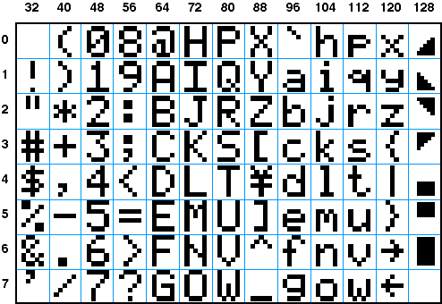 | Figure 4a.
Standard ASCII characters, by character code. |
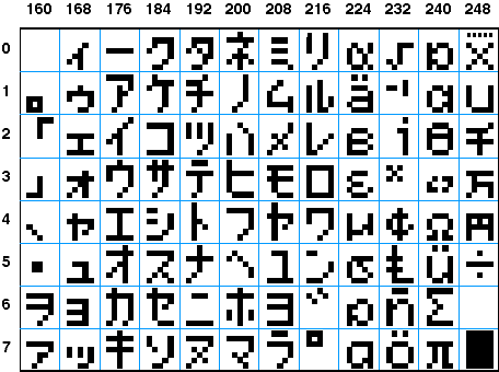 | Figure 4b.
High ASCII characters, by character code. |
The table below lists the special instructions, which control the TRM's nonvolatile memory, custom characters, and other special features. These are called escape sequences because they begin with the escape character (ASCII 27), which distinguishes them from normal text.
Most escape sequences follow the same basic pattern: escape-letter-number. For example, the escape sequence for displaying a screen stored in EEPROM is ESC E n, where n is a number from 0 to 94. From the keyboard, you would press the Escape key, then E, then a number key like 2, then a non-numeric key like the space bar. As soon as you press the space bar, EEPROM screen 2 would load into the display. The final, non-number character in the sequence, the space in our example, is thrown away; it does not affect the display except to signal the end of the number.
Numbers up to 191 may be sent as one-byte shortcuts. Just add 64 to the number and send that single-byte value. For example, to send the number 101, you could either send the three bytes "101" or a single byte containing the value 64 + 101= 165 (i.e., A5 hex; 10100101 binary). When you send multiple numbers as shortcuts, you do not need any characters to separate them, nor any throwaway character(s).
| Sequence |
Purpose/Effect |
| ESC D n b0 b1 b2 b3 b4 b5 b6 b7
| Define custom character n according to the bit patterns of bytes b0 through b7.
|
| ESC E n
| (Uppercase E) Display EEPROM screen n (0-94).
|
| ESC e n
| (Lowercase e) Retrieve a set of custom characters (0-7, 191) from EEPROM. ESC e 191 retrieves the special custom-character set needed for Control-B big character mode.
|
| ESC W {data}
| Write configuration data to EEPROM. Works only with jumper in CFG position. See the full description for the contents of {data}.
|
| ESC X n
| (Uppercase X) Transfer all text from the screen to EEPROM page (0-94).
|
| ESC x n
| (Lowercase x) Transfer current custom-character set to EEPROM page (0-7).
|
ESC D redefines one of the LCD's custom characters. The LCD has eight custom-character slots, numbered 0-7. These characters are mapped to ASCII codes 128 through 135. At startup, the unit loads these custom characters with shapes needed to support the Control-B Big Characters mode. Using the Define instruction, you can change a custom character. Send Escape (ASCII 27) followed by the letter D (ASCII 68), then the symbol number you wish to define (0�7, ASCII 48�55), followed by eight bytes defining the bitmap.
|
Calculate byte values for this instruction using the Javascript program on the right. Click pixels to toggle them on/off (browser must be version 4 or higher, with Javascript/Jscript turned on). The righthand bit of each row is the least-significant bit of the row byte.
HINT: Copy and paste the list of values into your program to save typing.
NOTE: Redefining custom characters will garble the Big Character mode, even big characters already on the screen. To restore the original custom characters, use ESC e 191, described below.
|
|
ESC E (uppercase E) recalls a stored screen from EEPROM and displays it on the LCD. Valid screen numbers are 0-94. Screen numbers may be sent as text followed by a throwaway character, or as single-byte shortcuts, as described in the Escape-sequence intro. If no screen is stored at the specified location, the LCD will usually fill with black blocks (since EEPROMs are generally filled with 1s when erased, and a byte containing all 1s equates to ASCII 255--the block character). To store a screen for use with ESC E, use the ESC X (uppercase) instruction described below. The free TRM-425 configuration program also lets you conveniently define and store screens using a Windows 95/98/NT PC.
ESC e (lowercase e) recalls a set of eight custom-character patterns from EEPROM and loads them into the LCD. Valid set numbers are 0-7 and 191. Set 191 is special: it is the default custom-character set required to generate big characters (Control-B mode). This set is store in ROM and cannot be changed. If your program has previously redefined individual custom characters, or used EEPROM character sets 0-7, use ESC e 191 before big-character mode.
Set numbers may be sent as text followed by a throwaway character, or as single-byte shortcuts, as described in the Escape-sequence intro. If no set is stored at the specified location, the characters will usually be changed to solid-black blocks (since EEPROMs are generally filled with 1s when erased, 1s represent dark pixels in custom-character patterns). To store character sets for use with ESC e, use the ESC x (lowercase) instruction described below. The free TRM-425 configuration program also lets you conveniently define and store character sets using a Windows 95/98/NT PC.
ESC W accepts 32 bytes of configuration data and writes it to the EEPROM. This instruction works only when a jumper is installed at CFG on the interface board. After a successful ESC W, the LCD will display a summary of the more-important 'hidden' settings. ('Hidden' in the sense that their effect is not readily visible. Backlight status and startup-screen settings are obvious when the display starts up; timing parameters for keypad scanning are not.)
The easiest way to perform ESC W configuration is by using the free configuration program, described in the next section. However, you may also configure TRM-425 with any computer capable of sending the appropriate data serially (see the BS2 program example). Here is a description of the 32-byte configuration:
| Byte # |
Function |
| b0-b15 |
Keypad characters 0-15. These are the ASCII codes that will be sent when the keys are pressed. With most keypads, byte 0 corresponds to the key at the lower-left corner of the pad, and bytes go left-to-right, bottom to top. However, if the pad has its row and column connections reversed, b0 will be at lower right with a bottom-to-top, right-to-left sequence. |
b16 |
Basic settings. Add up one choice from each option to arrive at the correct value for the byte:
- Baud Rate: 0=9600; 1=4800; 2=2400; 3=1200
- Cursor at Startup: 0=off; 8=underline; 12=block
- Backlight at Startup: 0=off; 16=on
- Write Protect EEPROM (prevent ESC X/x): 0=no; 32=protect
- Show EEPROM Screen 0 at Startup: 0=no; 64=yes
Example: For 9600 baud, underline cursor, backlight on, write-protect off and EEPROM screen 0 at startup, the byte value would be 0+8+16+0+64 = 88.
NOTE: Changes made to these settings do not take effect until the TRM is turned off and back on. The configuration screen will change to reflect the new baud rate value, but TRM will continue to work at its previous baud rate (until the power is cycled).
|
| b17 |
Powerup delay (in seconds). Some host computers can send garbage characters during their startup sequence. Setting a power-up delay slightly longer than the computer's maximum boot time causes TRM to ignore this garbage input. Default is 0. |
| b18 |
Control-G bell duration (in 0.512 ms units). When the Bell character (ASCII 7, control-G) is received, TRM pulses the buzzer output for the lenght of time set by b18. Default is approximately 100 ms (200 units). With a loud buzzer, a shorter setting may be better. |
| b19 |
Key scan interval (in 0.512 ms units). TRM checks for keypad activity at the interval set by b19. Default setting is 32, so the keypad is checked every 32 x 0.512 = 16.4 milliseconds or 61 times a second. For most keypads, this is an excellent balance between debounce and responsiveness. Higher settings cause less-frequent scanning. Minimum setting is 20 (approx. 100 scans/second). Suggestion: Don't change this value unless you have keypad problems, such as multiple responses to a single press. Fine-tuning the scan interval is usually a waste of time. |
| b20 |
Key bell duration (in 0.512 ms units). TRM can pulse the buzzer output in response to key presses, and b20 sets the length of the key-bell pulse. The default setting for b20 is 0 (no bell response to keys). If your application uses the control-G and the key-bell feature, it makes sense to set b20 and b18 to different values so that the two bells are audibly different. Suggestion: Set key bell for a short pip sound, (~ 50) and control-G bell for a longer, alert sound (~ 200). |
| b21 |
Key strobe duration (in 0.512 ms units). Default setting is 0, and should always be 0 when TRM is used with PCs or other computers with full-duplex serial ports (those with buffered send/receive capabilities). Only use a non-zero setting if you plan to use keypad handshaking (pin 6 of J1). When key strobe is 0, key presses are sent immediately. If key strobe is greater than 0, when a key is pressed, TRM puts a low (0) on pin 6 of J1. It holds pin6/J1 low for the length of time set by the key-strobe value. During this interval, the computer connected to J1 should have detected this low (0) and turned its I/O pin output-low too. When the interval ends, TRM looks for the low response on pin 6/J1; if it's there (low), TRM sends the keypress; otherwise TRM ignores the keypress. This allows non-duplex computers (e.g., the BASIC Stamp®) to poll for keypresses. The key-strobe interval should be set to the shortest time possible that will still allow the computer to avoid missing keypresses. This value may have to be determined by experimentation. |
| b22-31 |
Reserved. No function in current version. May be set to any value with no effect. |
ESC X (uppercase X) copies the current screen contents to location n (0-94) in EEPROM. This completely overwrites any previously stored screen in location n. Screens may be recalled using ESC E (above). Note that screens using custom characters (ASCII 128-135) must have the same custom-character patterns in effect when they are recalled. See ESC x (lowercase) and ESC e (lowercase) for methods of storing and recalling sets of custom characters.
Transfer Custom-character Set to EEPROM (ESC x n)
ESC x (lowercase x) copies the current set of custom characters to location n (0-7) in EEPROM. A custom character set consists of the bit patterns for ASCII 128 - 135, which may be customized using ESC D (above). ESC x completely overwrites any previously stored custom-character set in location n. Custom characters may be recalled from EEPROM using ESC e (lowercase) described above.
Using the information in the previous section it wouldn't be too difficult to write a program to configure the various EEPROM settings, screens, and character sets to your liking. However, in some applications you may want to download all EEPROM contents in one shot without additional programming. This disk includes Windows 95/98/NT-compatible software that lets you configure TRM-425 visually, by clicking buttons and entering values on a form. When your settings are complete, you can download them to the TRM through the PC's serial port, and save them to disk for future use.
The TRM configuration software is included on the disk that contains this manual. If you are viewing this manual online, click here to download a complete copy of the disk. Unlike most current Windows® programs, the software requires no formal installation procedure; just copy it to a convenient location on your hard drive and double-click to launch. To remove the program, drag it to the Trash/Recycle bin. It makes no changes to your system configuration.
To use the program, connect TRM to the PC comm port using TRM-CBL or the hookup shown in Figure 2. Install the jumper at "CFG" on the TRM interface board and connect power (e.g., the included 9V battery snap to pins 1/2 of J1). When TRM powers up in configuration (CFG) mode, it will display some of the settings currently in EEPROM.
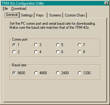
Launch the configuration program. It is organized like a tabbed notebook. Set comm port to the port number to which the TRM is connected. Set baud rate to match the TRM-displayed setting.
NOTE: If you use the software to change the TRM's baud-rate setting, this change will not take effect until the next time the display is powered up. Don't change the PC baud rate after initial setup, unless you turn the TRM off and back on.
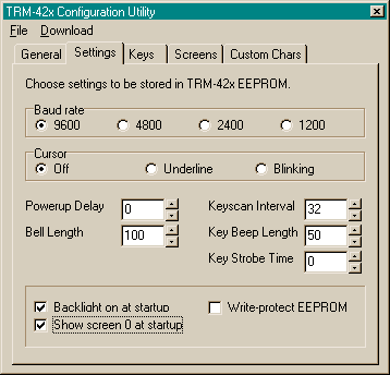
The Settings tab lets you set TRM's startup configuration. For in-depth explanations of the settings, see the description of ESC W above.
To load the settings into the TRM, use the Download menu, and select Settings/Keys. Before doing so, go to the Keys tab and edit the key codes to match your keypad.
You can assign one character to each key of the keypad using the text boxes on the Keys tab. The arrangement of boxes matches the most common keypad layout. In addition to standard (keyboard) characters, you may assign any ASCII code to a key. Select the contents of the text box, then right-click with your mouse. Enter the ASCII code in the window that pops up. Note that the character displayed will be the Windows font representation of the ASCII code--it may not match other character sets.
To load the settings into the TRM, use the Download menu, and select Settings/Keys.
Note that the text boxes on the Keys tab will accept only one character. If you click in a box that already contains a character, it won't accept another until you erase the current character. This applies to both typing and right-clicking.
The Screens tab accepts text screens for storage in the TRM's 95 EEPROM locations. Here are the steps for entering the data:
- Select an EEPROM location (0-94) using the arrow buttons.
- Enter and edit the text. (Right-click to enter special characters by ASCII code.)
- Press Preview on TRM to download the text to the TRM screen without storing it in EEPROM.
- Press Store to hold the text in a download buffer. If you don't press Store, the text will be discarded.
- Repeat these steps for all of the EEPROM locations that you want to program.
To load screens into the TRM, use the Download menu and select Screens. Only Stored screens will be downloaded to the TRM. This allows you to selectively update particular EEPROM locations without downloading all 95 screens. Note, however, that when you Open a previously Saved configuration file, all previously downloaded screens are automatically stored in the download buffer. Even if you edit only one of these screens, all will be downloaded.
Note that whenever you edit a screen its status changes to Not Stored.
The Custom Chars tab accepts custom character definitions for storage in EEPROM. TRM supports 8 sets of 8 custom characters. Here are the steps for entering the data:
- Select a character set (0-7) and character number (0-7) using the arrow buttons.
- Edit the character pattern, clicking the pixels to toggle them on/off.
- Press Preview on TRM to download the pattern and generate a test character on the TRM screen.
- Press Store to hold the pattern in a download buffer. If you don't press Store, the pattern will be discarded.
- Repeat these steps for all of the character sets that you want to program.
To load character sets into the TRM, use the Download menu and select Custom Chars. Only Stored characters will be downloaded. Characters are written into EEPROM on a set-by-set basis, so if you define one character in a set, you should define (Store) all of the characters in that set.
The File menu works in the usual way. Save lets you name and save a configuration file for future use. Open calls up a previously saved file. Exit quits the program.
The Download menu has three selections:
- Setting/Keys: Downloads data from the Settings and Keys tabs of the program.
- Screens: Downloads stored text screens from the Screens tab. Only screens marked "stored" are downloaded.
- Custom Chars: Downloads stored character bitmaps from the Custom Chars tab. If any one character within a set is stored, all characters will be reprogrammed. All character patterns in a set should be stored at the same time to avoid accidental loss of previously created patterns. If you have opened a previously saved configuration file, this is automatic.
TRM-425 is designed to speed prototyping and enable the creation of bench-top instruments requiring a serially driven text display and keypad interface. It is not meant for direct use by non-technical users or for incorporation into mass-produced consumer equipment. It has not been tested to EMC/EMI/ESD standards. (The same is true of most single-board computers and other subassemblies whose specs do not specifically include compliance data.) It is up to the purchaser to determine whether the unit is suitable for the intended use.
This unit is designed and manufactured to high standards of quality. This notice is simply intended to head off invalid assumptions that might affect decisions about using it in consumer products.
The following data is preliminary and subject to change without notice. The TRM-425 consists of two subassemblies--an LCD module, and a custom serial controller. Where the ratings of these two devices vary, the more conservative rating is shown in the table.
| Parameter |
min |
max |
typical |
unit |
| Operating temperature range |
0 |
+50 |
- |
°C |
| +32 |
+122 |
- |
°F |
| Storage temperature range |
20 |
+70 |
- |
°C |
| 4 |
+158 |
- |
°F |
| Supply voltage to J1, pin 2 ("9VDC") |
7.5 |
10.0 |
9.0 |
Vdc |
| Supply voltage to J1, pin 3 ("5V") |
4.50 |
5.50 |
5.00 |
Vdc |
| *Current draw, backlight off |
- |
20 |
10 |
mA |
| *Current draw, backlight on |
- |
60 |
40 |
mA |
| Processor clock speed |
- |
- |
16 |
MHz |
| *Note: Current draw specs apply to the 5V supply. Current drawn through the "9V" connector is approximately 10mA higher. |
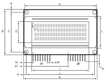
| A |
y offset edge to hole center (top & bottom) |
3.50 |
| B |
y pcb height |
47.00 |
| C |
y hole spacing |
40.00 |
| D |
y screen opening |
22.20 |
| E |
y character size |
4.00 |
| F |
x character size |
2.30 |
| G |
x offset pcb edge to hole center |
3.50 |
| H |
x screen frame |
76.20 |
| I |
x screen opening |
60.00 |
| J |
x hole spacing |
70.00 |
| K |
x pcb width |
77.00 |
| L |
y frame height |
32.60 |
| - |
mounting hardware (screw size/thread) |
4-40 |
- All dimensions in millimeters
- Tolerance is +/- 0.50mm
- Maximum depth (front of screen to highest point on pcb) is 28mm
|
LCDs can be damaged by careless handling. The manufacturer offers these suggestions for safe handling of LCDs:
- The LCD module and serial interface electronics use CMOS components and should be handled with appropriate antistatic precautions.
- Do not subject the LCD to temperatures outside its storage/operating ranges. Excessive heat or cold can degrade the polarizer, cause bubbles in the LCD material, or cause the polarizer to peel.
- Do not touch, push or rub the exposed polarizers (transparent screens) with anything harder than an HB pencil lead (glass, tweezers, etc.). Hard pressure on the screen may distort the liquid-crystal material. In some cases, the LCD will return to normal with time.
- Do not use glue, epoxy, silicone sealant, paint, etc. anywhere on the LCD. These contain solvents or corrosive substances that degrade contact surfaces over time. They can penetrate the LCD and damage elastomeric connectors and optical coatings.
- When the display surface becomes dusty, wipe gently with absorbent cotton or other soft material like chamois soaked in petroleum benzine. Do not scrub hard or you may damage the display surface.
- Wipe off saliva or water immediately. Contact with water over a long period of time may cause deformation or color fading.
- Don't allow the LCD to come into contact with oil and fats.
- Condensation on the surface and contact terminals due to cold will damage, stain or dirty the polarizers. After products are exposed to low temperatures they must be allowed to warm up before coming is contact with room-temperature air.
- Do not attach anything to the display screen. This may leave scratches or marks.
- Do not touch the display screen with bare hands. This will stain it. Skin oils and cosmetics are detrimental to the polarizers.
- Do not drop or jar the LCD module as you may crack or chip the glass.
Any computer/programming language that can communicate serially at 1200-9600 baud can drive the TRM-425. These examples are in BASIC, chosen because of its popularity and readability.
Summary: This program just prints a phrase on the display. It demonstrates clearing the screen and printing text.
Connections:
- BS2 Vss to TRM J1, pin 1
- BS2 Vin (9Vdc) to TRM J1, pin 2
- BS2 pin P0 to TRM J1, pin 4
Configuration: Check the TRM's baud setting (jumper CFG pins and connect power) and make sure that the program is set to match. Remove CFG jumper and cycle power before running this program.
Program Listing 1
' Program: TRMHELLO ("Hello World" demo for TRM-425/BS2)
' This program shows how to clear the screen
' and print text to the TRM-425.

' ===========Define Instruction(s)==========
CLRTRM	con	12	' Clear TRM screen.

' Uncomment (remove the ' mark from) the appropriate
' baud rate to match TRM baud setting. Comment
' out the others.
BAUD  	con	$054	' 9600 baud, BS2.
'BAUD 	con	$18D	' 2400 baud, BS2.
'BAUD  	con	$0F0	' 9600 baud, BS2-SX.
'BAUD 	con	$3FD	' 2400 baud, BS2-SX.

' ===========Begin demonstration=======
pause 1000				' Wait a sec.
serout 0,BAUD,[CLRTRM,"Hello World!"] 	' Clear, print text.
END	' Done. End program
Summary: This program demos various TRM text features.
Connections:
- BS2 Vss to TRM J1, pin 1
- BS2 Vin (9Vdc) to TRM J1, pin 2
- BS2 pin P0 to TRM J1, pin 4
Configuration: Check the TRM's baud setting (jumper CFG pins and connect power) and make sure that the program is set to match. Remove CFG jumper and cycle power before running this program.
Program Listing 2
' Program: TRMFEAT (Demo TRM-425 features with BS2)
' This program shows how to use some of the TRM-425's
' text-formatting features, including cursors,
' positioning, and big numbers.

'=========Define names for LCD instructions, bps=======
NOCURS	con	4 ' Make cursor invisible.
ULCURS	con	5 ' Show underline cursor.
CLRTRM	con	12 ' Clear entire LCD screen.
POSCMD	con	16 ' Position cursor.
CLRCOL	con	17 ' Clear column.
WEDGE 	con	128 ' Wedge-shaped symbol.
BIGNUM	con	2 ' Begin big numbers.

' Uncomment (remove the ' mark from) the appropriate
' baud rate to match TRM baud setting. Comment
' out the others.
BAUD  	con	$054	' 9600 baud, BS2.
'BAUD 	con	$18D	' 2400 baud, BS2.
'BAUD  	con	$0F0	' 9600 baud, BS2-SX.
'BAUD 	con	$3FD	' 2400 baud, BS2-SX.

' The constants "bell" and "bksp" are predefined in PBASIC2.

' =================Begin demonstration=================
pause 1000
serout 0,BAUD,[CLRTRM]	' Clear the screen.
for b2 = 0 to 79
  serout 0,BAUD,[WEDGE]	' Fill screen with wedges.
next
pause 1000 ' Wait 1 second.
serout 0,BAUD,[POSCMD,68] ' Move to position 4 (64+4= 68).
for b2 = 1 to 12	' Clear a 12-character swath with
  pause 350	' ...the clear-column feature.
  serout 0,BAUD,[CLRCOL,BELL] ' Ring bell (if available) each loop.
next

' Turn on the underline cursor, move to pos. 26, and show message.
serout 0,BAUD,[ULCURS,POSCMD,90,"4x20 LCD"]
pause 1000 ' Wait 1 second.
for b2 = 1 to 8
  pause 100 ' Backspace to erase message.
  serout 0,BAUD,[BKSP,BELL] ' Ring bell (if available) each loop.
next
pause 1000 ' Wait 1 second.
serout 0,BAUD,[NOCURS] ' Turn cursor off.

' Print the numbers 0 to 99 in big numbers in the middle of
' the screen. Pause a half second between numbers.
for b2 = 0 to 99
serout 0,BAUD,[POSCMD,70,BIGNUM,dec b2]
pause 500
next
END ' Finished.
Summary: This program demos the TRM keypad capability. It shows how the BS2 can detect a keypress and signal the TRM to transmit the key code. For a more complete explanation of the keystrobe function see Using the Keypad Capabilities.
Connections:
- BS2 Vss to TRM J1, pin 1
- BS2 Vin (9Vdc) to TRM J1, pin 2
- BS2 pin P0 to TRM J1, pin 4
- BS2 pin P1 to TRM J1, pin 5
- BS2 pin P2 to TRM J1, pin 6
Configuration: Check the TRM's baud setting (jumper CFG pins and connect power) and make sure that the program is set to match. The Key Strobe Time should be configured to 100. Remove CFG jumper and cycle power before running this program.
Program Listing 3
' Program: TRMKEY01 (Demo TRM-425 keypad with BS2)
' This program shows how the BS2 can receive key-
' presses from the TRM and echo them to the screen

'=========Define names for LCD instructions, bps=======
CLRTRM	con	12 ' Clear entire LCD screen.

' Uncomment (remove the ' mark from) the appropriate
' baud rate to match TRM baud setting. Comment
' out the others.
BAUD  	con	$054	' 9600 baud, BS2.
'BAUD 	con	$18D	' 2400 baud, BS2.
'BAUD  	con	$0F0	' 9600 baud, BS2-SX.
'BAUD 	con	$3FD	' 2400 baud, BS2-SX.

'=========Define variable(s)===========================
trmKey	var	byte	' Byte to hold key code.

' =================Begin demonstration=================
pause 1000			' Wait a sec.

' Clear the screen and print text.
serout 0,BAUD,[CLRTRM,"TRM keypad demo",cr]

' Now enter a loop that checks TRM keystrobe (on BS2
' pin P2) for key-press indication (0). If a press is
' detected, use serin to get it, then serout to display
' the key character on the TRM screen.
' = The "pause 50" is a 50-millisecond delay. It shows
' that the BS2 can be doing other processing and still
' pick up the keystrobe signal and fetch the key
' character.
again:
  input 2			' Set keystrobe input.
  pause 50
 if in2 = 1 then again	' No key press--loop.
  serin 1\2,BAUD,[trmKey]	' See note below
  serout 0,BAUD,[trmKey]	' Display key character.
goto again

' NOTE: The serin instruction above uses the little-known
' serin flow-control capability. "serin 1\2 ..." means
' "perform serial input on pin P1, using pin P2 for flow
' control by automatically setting P2 output-low when
' the BS2 is ready to receive." This is perfect for
' signalling the TRM to send the key character at the
' right time.
Summary: This program demos the TRM keypad with the BS2's numeric-input capability. It allows you to enter a number at the keypad and see it displayed on the screen. Note that this method is the simplest for accepting numeric intput, but not necessarily the best. Its main shortcoming is that digits are not displayed as they are entered. See the next example for a better way.
Connections:
- BS2 Vss to TRM J1, pin 1
- BS2 Vin (9Vdc) to TRM J1, pin 2
- BS2 pin P0 to TRM J1, pin 4
- BS2 pin P1 to TRM J1, pin 5
- BS2 pin P2 to TRM J1, pin 6
Configuration: Check the TRM's baud setting (jumper CFG pins and connect power) and make sure that the program is set to match. Also make sure that the keypad is configured with both numeric (0-9) and non-numeric key characters. Finally, be sure that the Key Strobe Time is set to a non-zero value (100 is good). Remove CFG jumper and cycle power before running this program.
Program Listing 4
' Program: TRMKEY02 (Demo TRM-425 keypad with BS2)
' This program shows how the BS2 can accept numeric
' input from the keypad. It assumes that the key
' character definitions include numbers (0-9) and
' non-numeric characters, and that the keystrobe
' value is set to 100.
' Note that this method of numeric input does
' not echo back to the screen until the entire
' number is entered and a non-numeric key is pressed.
' Another demo presents a more sophisticated method
' that requires a little bit more code.

'=========Define names for LCD instructions, bps=======
CLRTRM	con	12 ' Clear entire LCD screen.

' Uncomment (remove ' mark from) the appropriate
' baud rate to match TRM baud setting. Comment
' out the others.
BAUD  	con	$054	' 9600 baud, BS2.
'BAUD 	con	$18D	' 2400 baud, BS2.
'BAUD  	con	$0F0	' 9600 baud, BS2-SX.
'BAUD 	con	$3FD	' 2400 baud, BS2-SX.

'=========Define variable(s)===========================
numVal	var	word	' Numeric value input from keys.

' =================Begin demonstration=================
pause 1000			' Wait a sec.

begin:
' Clear the screen and print text.
serout 0,BAUD,[CLRTRM,"Enter a number:",cr]

' Now use Serin to gather input from TRM and convert
' it to a decimal number. Note that we are not checking
' for keypresses--"Serin 1\2.." automatically holds
' pin P2 low to tell TRM to send keypress data
' whenever it's available.
again:
  serin 1\2,BAUD,[DEC numVal]	' Get number
  serout 0,BAUD,[CLRTRM,"You entered: ", DEC numVal,cr,cr]
  serout 0,BAUD,["Press any key",cr, "to continue"]
  input 2			' Set keystrobe input.
hold:
  if in2 = 1 then hold	' No key press--loop.
  pause 100			' pause to discard key input.
goto begin
Summary: This program demos numeric input with the TRM keypad and BS2. The method demonstrated here, while a little more complicated than the previous example, allows the user to see the number as it is input, and to edit it by backspacing with the "*" key.
Connections:
- BS2 Vss to TRM J1, pin 1
- BS2 Vin (9Vdc) to TRM J1, pin 2
- BS2 pin P0 to TRM J1, pin 4
- BS2 pin P1 to TRM J1, pin 5
- BS2 pin P2 to TRM J1, pin 6
Configuration: Check the TRM's baud setting (jumper CFG pins and connect power) and make sure that the program is set to match. Also make sure that the keypad is configured with both numeric (0-9) characters and "*" and "#" (used as backspace and enter keys, respectively. Finally, be sure that the Key Strobe Time is set to 100. Remove CFG jumper and cycle power before running this program.
Program Listing 5
' Program: TRMKEY03 (Demo TRM-425 keypad with BS2)
' This program shows how to accept numeric
' input from the keypad and allow editing of a
' number as it is entered. It assumes that the key
' character definitions include numbers (0-9) and
' the symbols * and #, and that the keystrobe
' value is set to 100.
' The * key is used to backspace for corrections;
' the # key enters the number.

'=========Define names for LCD instructions, bps=======
CLRTRM	con	12 ' Clear entire LCD screen.
BKSPKEY	con	"*"	' Backspace key
ENTERKEY	con	"#"	' Enter key

' Uncomment (remove the ' mark) the appropriate
' baud rate to match TRM baud setting. Comment
' out the others.
BAUD  	con	$054	' 9600 baud, BS2.
'BAUD 	con	$18D	' 2400 baud, BS2.
'BAUD  	con	$0F0	' 9600 baud, BS2-SX.
'BAUD 	con	$3FD	' 2400 baud, BS2-SX.

'=========Define variable(s)===========================
keyIn 	var	byte	' Digit entered at keypad.
numVal	var	word	' Numeric value input from keys.

' =================Begin demonstration=================
pause 1000			' Wait a sec.

begin:
' Clear the screen and print text.
serout 0,BAUD,[CLRTRM,"Enter number:",cr]
numVal = 0	' Clear numVal to accept new value.

' Now enter a loop that checks TRM keystrobe (on BS2
' pin P2) for key-press indication (0).
again:
  input 2			' Set keystrobe input.
  pause 50			' Simulate other processing.
  if in2 = 1 then again	' No key press--loop.
  serin 1\2,BAUD,[keyIn]	' Get number
  if keyIn = BKSPKEY then backspace	'
  if keyIn = ENTERKEY then enter
  if keyIn < "0" then again	' Reject non-numbers
  if keyIn > "9" then again
' The next line multiplies numVal by 10 (shifting its
' value one decimal position to the left), and adds
' the value of the current key. Subtracting "0"
' converts the key's ASCII code to its numeric value.
  numVal = numVal * 10 + (keyIn - "0")
  serout 0,BAUD,[keyIn]
goto again

' If the backspace key (*) is pressed, divide accumulated
' numVal by 10 (to remove ones-place digit value) and
' echo a backspace character to the display.
backspace:
  numVal = numVal/10
  serout 0,BAUD,[BKSP]
goto again

' If the enter key (#) is pressed, clear the screen and
' announce the value of numVal. Then wait for a keypress
' to resume the program from the beginning.
enter:
  serout 0,BAUD,[CLRTRM,"You entered: ", DEC numVal,cr,cr]
  serout 0,BAUD,["Press any key",cr, "to continue"]
  input 2			' Set keystrobe input.
hold:
  if in2 = 1 then hold	' No key press--loop.
  pause 100			' pause to discard key input.
goto begin
Summary: This program lets you change the TRM's configuration settings with a BS2.
Connections:
- BS2 Vss to TRM J1, pin 1
- BS2 Vin (9Vdc) to TRM J1, pin 2
- BS2 pin P0 to TRM J1, pin 4
Configuration: Install a jumper at CFG on the TRM board before connecting power. When power is connected, you will see the configuration screen. Check the TRM's baud setting (jumper CFG pins and connect power) and make sure that the program is set to match. Change the values sent to the TRM by editing the program below the line marked "Begin configuration."
Program Listing 6
' Program: TRMCFG (Configure TRM-425 with BS2)
' This program allows you to confirgure the TRM's
' EEPROM-stored settings with a BS2. Although the
' PC-based configuration program is much more
' convenient, there may be times when it's too much
' bother to disconnect the TRM from the BS2 just to
' change a few setttings.
' =To use this program, install a jumper at CFG on
' the TRM board before connecting power. Modify the
' program listing where indicated below to send the
' desired setting. Run the program.

'=========Define names for LCD instructions, bps=======
CLRTRM	con	12	' Clear entire LCD screen.
ESC		con	27	' Escape character

' Uncomment (remove the ' mark from) the appropriate
' baud rate to match TRM baud setting. Comment
' out the others.
BAUD  	con	$054	' 9600 baud, BS2.
'BAUD 	con	$0BC	' 4800 baud, BS2.
'BAUD 	con	$18D	' 2400 baud, BS2.
'BAUD 	con	$32D	' 1200 baud, BS2.

'BAUD  	con	$0F0	' 9600 baud, BS2-SX.
'BAUD  	con	$1F4	' 4800 baud, BS2-SX.
'BAUD 	con	$3FD	' 2400 baud, BS2-SX.
'BAUD  	con	$80F	' 1200 baud, BS2-SX.

' Configuration constants==============================
'
B_96		con	0	' TRM config: 9600 baud
B_48		con	1	' TRM config: 4800 baud
B_24		con	2	' TRM config: 2400 baud
B_12		con	3	' TRM config: 1200 baud

CURSOFF	con	0	' Cursor off at startup
CURSUL	con	8	' Cursor = underline
CURSBLK	con	12	' Cursor = block

BL_OFF	con	0	' Backlight off at startup
BL_ON		con	16	' Backlight on

EEWRITE	con	0	' OK to write EEPROM
EELOCK	con	32	' Write-protect EEPROM

BLANK		con	0	' Screen blank at startup
SPLASH	con	64	' Show EEPROM screen 0 at start

'=========Define variable(s)===========================
bpsFlags	var	byte	' Baud rate and bit flags.
pwrDelay	var	byte	' Delay in seconds after startup.
bellDur	var	byte	' Buzzer duration, 0.5-ms units
keyInt	var	byte	' Key scan interval, 0.5-ms units
keyBell	var	byte	' Key beep duration, 0.5-ms units
keyStr	var	byte	' Key strobe duration, 0.5-ms units

' =================Begin configuration=================
pause 1000

serout 0,BAUD,[ESC,"W"]	' ESC-W starts config process.

' In the instruction below, list the characters you
' want returned by the keypad, starting at the lower
' left and working bottom-to-top. There must be 16
' entries, even if your keypad is smaller than 16
' keys (pad the unused positions with any character--
' say Xs--to make sure there are 16 entries.
serout 0,BAUD,["*0#D789C456B123A"]

' Now add up the option values listed above under
' Configuration Constants in bpsFlags:
bpsFlags = B_96+ CURSOFF+ BL_ON+ EEWRITE+ SPLASH

' Next, set the various timing values. Change these
' settings as desired. The values listed below work
' well with the example programs.
pwrDelay	=	0	' Delay in seconds after startup.
bellDur	=	100	' Buzzer duration, 0.5-ms units
keyInt	=	32	' Key scan interval, 0.5-ms units
keyBell	=	20	' Key beep duration, 0.5-ms units
keyStr	=	100	' Key strobe duration, 0.5-ms units

' Now send to the TRM. The instruction ..rep "x"\10.. just
' pads the unused bytes of the configuration memory with
' an arbitrary value, "x".
serout 0,BAUD,[bpsFlags,pwrDelay,bellDur,keyInt,keyBell,keyStr,rep "x"\10]

STOP	' Done.