
Displaying Wind Data with SGX-120L
Serial Graphics LCD and BASIC Stamp II
(SGX-120L has been discontinued for many years; reference only.)
This application note demonstrates several methods of presenting data on the SGX-120L serial graphics LCD (part number SGX-120L) using a BASIC Stamp IImicrocontroller. This example uses simulated wind speed and direction data, but the techniques can be applied to many other kinds of data.
The application demonstrates several key features of the SGX-120L, including:
- Using graphics screen(s) stored in EEPROM
- Editing the character set
- Using different font sizes
- Plotting points and drawing lines
- Creating a moving-needle display (e.g., meter or compass)
Downloadable Files
You may download the BASIC Stamp II program and the two graphics screens required by this application through this link.
Overview of the Application
Wind speed and direction change constantly, so they can be tough to present properly on a plain alphanumeric display. Using a graphics display, we can add a simulated weather vane and wind sock to the normal readouts of X miles per hour and Y degrees of bearing. See the photo.
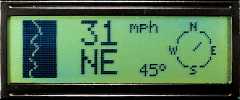
The SGX-120L display shows the wind speed as a number of mph, and as a vertical strip-chart of recent gusts along the left edge of the display. Wind direction appears as text (e.g., "NE" for northeast), a number of degrees, and as a pointer in a simulated wind vane.
First Steps
A smart first step in designing an application like this is to determine what portions of the screen display will change when the program runs, and what portions will remain the same. You can draw the unchanging screen elements in a paint program and load them into the display's EEPROM for instant, one-instruction retrieval. This may save many lines of code in your program.
In this case, we needed the wind-vane dial on the right, and a solid black rectangle on the left, so we created the picture below and loaded it into the SGX-120L's EEPROM at page 7 using the downloading software included with the display.

While working on the graphic, we made notes of the x and y coordinates of some important places on the display: the center point of the wind vane and the end points for the pointer in 16 positions around the 'dial.' The program uses lookup tables of coordinates to determine how to draw the pointer in each of the various directions (north, north-northeast, northeast...)
For the numeric display of the wind direction, we needed a degree symbol (°r;), which was not included in SGX-120L's original font. To add one, we opened the file CHARS1.BMP from the disk that came with the display, and drew a tiny circle in the next empty character position, ASCII 128. Once that file was loaded into the SGX-120L's EEPROM page 1, ASCII 128 would always display the °r; s ymbol. (There's nothing magic about that position--the symbol could have been added anywhere.)
The BASIC Stamp II (BS2) Hardware
Without a working weather station on the premises, we had to simulate the wind inputs. To this end, we hooked a couple of potentiometers to the BS2 as shown in the diagram below. Twiddling the pots simulates changes in wind speed and direction. In the BS2 program, we put the code that reads the pots in subroutines for easy modification. If we ever do put in a weather vane and anemometer, getting live data into the display will be a simple matter of substituting the appropriate code in the program.
A note regarding the 5V power supply: The SGX-120L display has an LED backlight. When it's off, the unit draws about 10mA. When the backlight is on, current draw can range as high as 65 mA. This is more current than the BS2's built-in voltage regulator can provide. Our example program doesn't turn on the backlight. If you want to use the backlight, you may:
- connect both the BS2 and SGX-120L to a single, husky 5V power supply, OR
- power the BS2 through its 9V battery input and the SGX-120L through its 9V input
If you pick the second option, be sure that the +5V (Vdd) terminals of the BS2 and the display are not connected together.
The BS2 Program
The program is pretty thoroughly commented, but there are a few subtleties worth pointing out:
- The arguments (data) that are fed to the LCD instruction like those that set the font, plot lines, etc., are all expressed in what we call '1-byte shortcuts.' All that amounts to is a single byte containing the number to be sent + 64. Values from 0 to 191 can be expressed this way. The SGX-120L can also accept values in terms of normal text. So you could express the value 123 as either the text string "123" (as you would type it) or as a single byte set to 123 + 64 = 187 (10111011 binary). Speed is the primary advantage of using shortcuts; instead of sending 3 bytes of text, you send just 1 byte. Why add 64 to create the shortcut? In the ASCII character set, the symbols for the numbers "0" through "9" are assigned to the value 48-57; adding 64 to a byte value makes sure that it won't be misinterpreted as numeric text.
- The two numeric text fields--wind mph and bearing in degrees--are right-aligned using a SGX-120L instruction. This instruction automatically pads a given snippet of text (usually a number) with leading spaces so that it is right-aligned up to the current screen position. The leading spaces also erase any leftover text or digits within that area of the screen. The subtle thing here is that you must terminate the instruction with either a period ("." for decimal-aligned numbers) or with a harmless control character. We use a control-C, which doesn't do anything in this case except flag the end of the right-alignment mode.
- All data is sent to the display with the BS2's serout instruction. This instruction accepts a list of items to be transmitted serially. Anything in quotes is sent as text. Numbers by themselves (without any modifiers) are sent as single byte; e.g. 65 is set as 01000001 binary. Adding a modifier before a number tells the BS2 to convert it into text; e.g. DEC 65 sends the text string "65". Named constants like CLR con 12 are treated just like any other number. Once the constant CLR is defined as 12, the number 12 is substituted wherever CLR is used. Finally, every serout instruction takes some code-space overhead, so it pays to cram as many items as possible into each serout list.
- At the very beginning of the program, there's a serout instruction that sends several shortcut zeros followed by a clear screen instruction. The idea is that during program development you're likely to interrupt the program at any point. Suppose that the display had just begun a line-plot instruction. It would be waiting for 4 values to complete the instruction. That could cause it to misinterpret data sent after the reset by trying to use that data to finish the line-plot instruction. Sending those shortcut zeros completes any pending instructions; immediately clearing the screen prevents you from ever seeing the result.
Program Listing
' Program: WND_GX1.BS2 (Display wind direction and speed)
' This program demonstrates the SGX-120L serial graphics LCD
' with the Parallax Basic Stamp II (R). It assumes that the SGX-120L
' is set for 9600 bps (switch on pcb to "9600") and that it is
' connected to the Stamp as follows:
'            SGX-120L                   Stamp
'            -----------------       ---------
'            SER (serial in)         I/O pin P0
'            GND (ground)            Vss/GROUND
'            +5                      Vdd/+5V
' For the demo, we've also connected a couple of pots to pins P6 and
' P7 of the BS2. These simulate inputs from the wind direction and
' speed sensors. For this simulation, we use 10k pots and 0.1uF
' caps, with the caps wired to +5V as shown in the rctime section
' of the Stamp II manual.

' Before running this program, a couple of new EEPROM images must
' be downloaded to the display; EEPROM page 7 should be loaded with
' graphic WIND1.BMP, and EEPROM page 1 with a versions of CHARS1.BMP
' that has been edited to include a degree symbol at the end of
' the font (ASCII 128). See the accompanying text.

' ===========Define names for LCD instructions==========
CLR     con     12      ' Clear entire LCD screen.
CTLC    con     3       ' Control-C: control character to end right-align.
POS     con     16      ' Position cursor.
RTALGN  con     18      ' Right-align.
ESC     con     27      ' Escape code for graphics instructions.
n9600   con     $4054   ' Baudmode for 9600 bps, inverted.
CUT0    con     64      ' 1-byte shortcut for 0 (64+0 = 64)
SCRN7   con     71      ' 1-byte shortcut for 7 (EEPROM screen 7)
CNTRX   con     169     ' X coord of wind vane center (as shortcut #).
CNTRY   con     80      ' Y coord "  "    "    "      "   "        "
XMAX    con     20      ' Max value for graph X coord.
BIG     con     67      ' Shortcut for 3 (big font).
SMALL   con     64      ' Shortcut for 0 (small font).
BLACK   con     65      ' Shortcut for 1 (black ink)
WHITE   con     64      ' Shortcut for 0 (white ink)
DEGR    con     128     ' ASCII code for degree symbol added to font.

' ===========Variables==================================
newDir  var     nib     ' Current wind direction (0-15; 0 is North).
theDir  var     nib     ' Old direction--use by lookup.
tenths  var     nib     ' Tenths of a degree.
pointX  var     byte    ' X coord of pointer end.
pointY  var     byte    ' Y coord of pointer end.
rawDir  var     word    ' Unscaled input from direction sensor.
rawSpd  var     word    ' "        "     "    speed     "
bearing var     word    ' Wind direction in degrees.
wndMPH  var     byte    ' Wind speed in miles/hour.
ripY    var     byte    ' Current Y position of ripple graph.
x1      var     byte    ' 1st X coord for line plot
y1      var     byte    ' 1st Y coord for line plot
x2      var     byte    ' 2nd X coord for line plot
y2      var     byte    ' 2nd Y coord for line plot
dirSt   var     byte(3) ' Three-byte string for wind direction.

' ===========EEPROM Strings=================================
' These are three-letter abbreviations for the 16 compass
' points covered by our wind-direction indicator. By making
' all of the abbreviations three bytes long, we can easily
' select the appropriate string's starting point (3 times
' the wind direction).
N       data    " N "   ' North
NNE     data    "NNE"   ' North-Northeast
NE      data    " NE"   ' Northeast
ENE     data    "ENE"   ' East-Northeast
E       data    " E "   ' East
ESE     data    "ESE"   ' East-Southeast
SE      data    " SE"   ' Southeast
SSE     data    "SSE"   ' South-Southeast
S       data    " S "   ' South
SSW     data    "SSW"   ' South-Southwest
SW      data    " SW"   ' Southwest
WSW     data    "WSW"   ' West-Southwest
W       data    " W "   ' West
WNW     data    "WNW"   ' West-Northwest
NW      data    " NW"   ' Northwest
NNW     data    "NNW"   ' North-Northwest

' ===========================================================
'                         INITIALIZATION
' ===========================================================
' The line below is not really necessary except during
' interactive programming. It's purpose is to complete any LCD
' instructions that you may have interrupted by typing alt-R or
' pressing the BS2 reset button. When the program starts again,
' the LCD may be waiting for data to complete those instructions.
' The line below supplies dummy data, then immediately clears the
' screen.
serout 0,n9600,[CUT0,CUT0,CUT0,CUT0,CLR]

pause 1000      ' Wait a sec for LCD startup.

' Clear the LCD and call up EEPROM image 7, which is preloaded
' with the compass dial image.
serout 0,n9600,[CLR,ESC,"E",SCRN7,ESC,"F",SMALL,POS,75,"mph"]

' To prevent the program from needlessly erasing and redrawing the
' wind-direction pointer, the showWindDir routine draws only when the
' new direction is not the same as the old. To make sure that the
' very first direction reading draws, we take an initial reading,
' put the inverse in the old direction, and show. This 'primes
' the pump.'

gosub getWindDir: theDir = ~newDir:gosub showWindDir

' ===========================================================
'                         MAIN PROGRAM
' ===========================================================
' The main program is an endless loop that continuously acquires
' and displays the wind data. Subroutines handle all the
' engine-room details, making it easy to modify the program.
again:
  gosub getWindDir      ' Read wind-direction sensor.
  gosub showWindDir     ' Display the wind direction.
  gosub getWindSpd      ' Read wind-speed sensor
  gosub showWindSpd     ' Display the wind speed.
  pause 100             ' Slow the update rate to prevent jitters.
goto again


' ===========================================================
'                  Display Wind Speed
' ===========================================================
' ShowWindSpd plots a vertical strip chart on the left edge
' of the screen to show short-term trends in wind speed.
' The graph is continuously updated, like an oscilloscope,
' so a black line is used to erase the oldest data on the screen.
' The routine also prints the wind speed as a three-digit number
' using the big font size and right-alignment feature.
showWindSpd:
' Plot a white point whose distance from the left edge of the
' screen is proportional to the wind speed. Each pixel is 5mph.
' White pixels are plotted against a black background.
x1 = cut0: y1 = ripY + cut0
x2 = wndMPH/5 max xMax + cut0
serout 0,n9600,[ESC,"I",WHITE,ESC,"P",x2,y1]

' Now increment to the next vertical (y) position and print a black
' line to erase old data in preparation for the next plot. ANDing
' the y value with 31 (..& 31) makes it wrap around the screen
' vertically, since the screen y coordinates are 0-31.
ripY = ripY + 1 &31
y1 = ripY + cut0
x2 = xMax + cut0
serout 0,n9600,[ESC,"I",BLACK,ESC,"L",x1,y1,x2,y1]

' Finally, print the wind speed in the big font on the top line
' (position 5) in a right-aligned field 3 characters wide.
' terminate the right-align mode with a control-C.
serout 0,n9600,[ESC,"F",BIG,POS,69,RTALGN,"3",DEC wndMPH,CTLC]
return

' ===========================================================
'                  Display Wind Direction
' ===========================================================
' ShowWindDir draws the wind-direction needle by erasing the
' previous needle and drawing in a new one. The present direction
' must be in newDir; the old direction will be in theDir--the
' variable used by the lookup tables in getPointerCoords.

showWindDir
' If the direction is unchanged from the last plot, then return
' without updating the screen. This prevents the pointer from
' flickering as a result of being erased and redrawn in the
' same location.
if newDir <> theDir then updateDir
return          ' If no change, return now.
updateDir:      ' Otherwise update the screen.
gosub convertWindDir
' Erase the old direction pointer with a white line from center to
' the old endpoint.
serout 0,n9600,[ESC,"I",WHITE,ESC,"L",CNTRX,CNTRY,pointX,pointY]
' Put the new endpoint into the one used by the 'convert' routine
' and plot the new pointer in black.
theDir=newDir
gosub convertWindDir
serout 0,n9600,[ESC,"I",BLACK,ESC,"L",CNTRX,CNTRY,pointX,pointY]

' Text display of wind direction: The convertWindDir routine loaded
' the three-letter abbreviation for the wind direction into the
' bytes of dirSt(). The following line sets the big font and
' printing position, then outputs the three bytes.
serout 0,n9600,[ESC,"F",BIG,POS,76,dirSt(0),dirSt(1),dirSt(2)]

' Numeric display of wind direction: ConvertWindDir loaded the wind
' direction in degrees into the variable bearing. The following line
' sets the small font, moves to screen position 74 (64+74 = 138),
' requests right-alignment within a 3-character space, then
' prints the bearing as a decimal number. To terminate the right-align
' mode, it sends an unused control character (ctlC). After the bearing,
' it sends ASCII 128, which we've defined as the degree symbol by
' editing and downloading EEPROM page 1.
serout 0,n9600,[ESC,"F",SMALL,POS,138,RTALGN,"3",DEC bearing,CTLC,DEGR]
return

' ===========================================================
' ConvertWindDir looks up the endpoint coordinates for the
' wind-direction pointer based on the contents of variable
' theDir. The coordinates are returned in pointX and pointY.
' Note that all coordinates are expressed as single-byte
' shortcuts (byte values of 64+n) for fast transmission to the
' SGX-120L display. Another lookup table gets the bearing in
' degrees. And a series of Read instructions get the 3-letter
' abbreviations for wind direction from EEPROM.
convertWindDir:
  lookup theDir,[169,171,173,174,174,174,173,171,169,167,165,164,164,164,165,167],pointX
  lookup theDir,[75,75,76,78,80,82,84,85,85,85,84,82,80,78,76,75],pointY
  lookup theDir,[0,22,45,67,90,112,135,157,180,202,225,247,270,292,315,337],bearing
  read (theDir*3), dirSt(0)     ' 1st byte of string into dirSt(0)
  read (theDir*3 +1), dirSt(1)  ' 2nd "    "  "      "    "    (1)
  read (theDir*3 +2), dirSt(2)  ' 3rd "    "  "      "    "    (2)
return

' ===========================================================
'                Get Wind Direction and Speed
' ===========================================================
' A couple of pots are wired to provide simulated wind speed and
' direction data. In an actual application, these routines
' would be replaced with the appropriate code to acquire and scale
' the wind data. For this simulation, we use 10k pots and 0.1uF
' caps, with the caps wired to +5V as shown in the rctime section
' of the Stamp II manual.
getWindDir:             ' Output 0-15 in newDir, where 0 is due north.
  high 6: pause 1       ' Discharge cap on pin 6.
  rctime 6,1,rawDir     ' Measure charge time (approx. 0-600)
  newDir = rawDir/40    ' Scale to simulate direction (0-15)
return

getWindSpd:             ' Output 0-999 in wndMPH (3-digit miles/hour).
  high 7: pause 1       ' Discharge cap on pin 7.
  rctime 7,1,rawSpd     ' Measure charge time (approx. 0-600)
  wndMPH = rawSpd/5     ' Scale to simulate wind speed (0-120)
return