
Connectors for Serial Displays
The standard connector used on most of our serial LCDs--a 5-pin male header--is versatile and easy to use. This app note supplies additional hookup hints and tips for prototypers and manufacturers that go beyond the information in the user manuals.
Ready-made made wiring harnesses that fit most of our displays are available for purchase online.
The header connector
Our standard connector consists of five 0.025-inch square header posts on 0.1-inch centers. The five posts make only three electrical connections: +5V, GND, and SER(ial data in), laid out as follows:
| +5V | GND | SER | GND | +5V |
 The advantage of this layout should be
obvious--there's no wrong way to install a matching
connector. In addition to being less cumbersome than a polarized
connector, this mirrored or pallindrome layout is actually
more fool-proof. Hurried technicians frequently overpower
key-and-notch arrangements or ignore alignment marks.
The advantage of this layout should be
obvious--there's no wrong way to install a matching
connector. In addition to being less cumbersome than a polarized
connector, this mirrored or pallindrome layout is actually
more fool-proof. Hurried technicians frequently overpower
key-and-notch arrangements or ignore alignment marks.
Breadboard and Proto Hookup
In a breadboard or prototype setup, you can make a quick connection by wire-wrapping or soldering hookup wires to the posts. For neater, removable connections consider using our jumper wires (CNX-010; $6/pkg of 10). These are flexible hookup wires with a female header socket at each end; the sockets slip right onto the 0.025-inch header posts.
If you do a lot of work with electronic devices that use header post connectors, it's worthwhile to purchase a tool and learn how to make crimp-socket connectors yourself. See the crimping tutorial below.
More Permanent Connections
If your project becomes a product, you will want an easy-to-install wiring harness. Here are a couple of the more popular options:
AMP Flex Cables
AMP makes an excellent connector system for header posts that's marketed through Digi-Key. Known as Flat Flex Cable Assemblies, these consist of a thin polyester ribbon with embedded copper-foil conductors on 0.1-inch centers:
Digi-Key stocks two flavors of this item that are of interest to us:
- 0.026-inch solder tabs (on 0.1-inch centers) to 5-pin header socket (part number A9BAG-050*F-ND)
- 5-pin header socket to 5-pin header socket(part number A9BBG-050*F-ND)
In those part numbers, substitute the length in inches for the *. Standard lengths are 2,3,4,5,6, and 8 inches; custom lengths are possible by arrangement with Digi-Key.
The AMP cable system is most appropriate when you plan to design a printed circuit board for your product. You would lay out five pads on 0.1-inch centers to accommodate either solder tabs or a row of header posts.
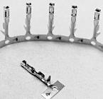
Discrete Wires with Crimp Sockets
If you need to connect the display to an existing wiring harness, or just prefer the flexibility of using separate wires to make the hookup, crimp-on header sockets and housings may be the better choice. Digi-Key also carries some products in this line, by Molex-Waldom and AMP, but we'll use products from Jameco to illustrate the idea. Basically, you begin by crimping header sockets onto the ends of stranded hookup wire (22-26 AWG), then snap the sockets into small plastic housings, like so:
Here are the Jameco part numbers for this type of connector:
- Crimping tool: part no. 99443
- Crimp-on sockets: part no. 100766
- 5-cell housing: part no. 163686
- 22-AWG stranded hookup wire (black, 100'): part no. 126084
- 22-AWG stranded hookup wire (white, 100'): part no. 126076
- 22-AWG stranded hookup wire (red, 100'): part no. 126033
The Art of Crimping
Crimping tools come in a wide range of prices and types, but they have one thing in common: none includes instructions. The better the tool, the less skill and attention required to use it. For example, if you're going to make a lot of header-socket assemblies, consider getting a nice tool like OEM Crimp Tool, part no. 694PR135 from Techni-Tool.
For less demanding use, inexpensive tools work just fine. The primary differences between pro and amateur tools are:
- The OEM tool makes two specialized crimps--one for gripping the wire's insulation, and another for making electrical contact between the connector and the bare wire. The budget tool makes just one kind of crimp that forms a flattened oval tube. To ensure good electrical contact, you have to pinch this tube down on the bare wire in a second step.
- The OEM tool has a ratchet that won't allow you to open the tool until you have cycled it through a complete crimp motion. This helps prevent bad crimps, and reduces fatigue. The budget tool is just like a pair of pliers--you have to squeeze hard and hope that you've squeezed hard enough.
The steps shown here are for the budget tool. If you get a better tool, the same basic process applies, but you won't have to pre-form the connector wings, and you won't have to pinch the wire-contact afterwards.
 |
(1) Crimp sockets (pn 100766) come on a metal ammo belt. It's helpful to leave a bit of this metal attached to the connector for use as a handle. | 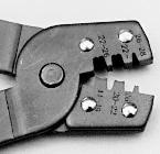 |
(2) Budget crimp tool (pn 99443). When you squeeze the handles, those metal teeth push the crimp connector up into a die, which forms the crimp. |
 |
(3) Strip 1/4" from the end of the wire. Lay the wire into the groove at the base of the socket. Line up the insulation with the longer wings. | 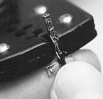 |
(4) Gently pinch the wings closed a bit. If they're too wide, they won't go into the die properly. |
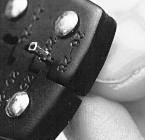 |
(5) Lay the connector against the smallest tooth with the wings facing into the die. Squeeze hard. | 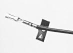 |
(6) Done. After crimping, pinch the metal covering the bare portion of the wire with the very tips of the tool. This ensures good contact. |