Practical Tips on Serial Communications
In many cases getting serial output from a computer or controller is a no-brainer. You don't need to know how it works--just hook up to a designated port or pin and there you are. But when you're building from scratch or troubleshooting a poorly documented system it can be valuable to understand some under-the-hood details. That's where this app note comes in.
RS-232 and Variations
RS-232 is a standard that describes a common method of serial signalling using a voltage that switches between a positive level for logic "0" and a negative level for logic "1". Per the standard,
- +2.5 to +15V = logic 0
- -2.5 to -15V = logic 1
Many products fudge on the standard. For example, a system without a negative power supply may define it this way:
- +5V = logic 0
- 0V = logic 1
Serial outputs generated by the BASIC Stamp and non-UART-equipped microcontrollers often use this approach, since it saves the cost of a serial line-driver IC.
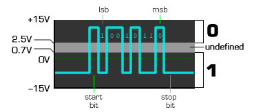
Serial inputs on our products work fine with either real RS-232 (+/-15V), or its logic-level counterpart (0-5V). Our products' approximate serial logic thresholds are:
- +2.5 to +15V = logic 0
- +0.7 to -15V = logic 1
 |
| Figure 1. Simulated RS-232 signal and serial logic thresholds for our products. |
Tips to Remember
Just knowing a little about the signalling voltages gives you a few strong hints for troubleshooting and design:
- RS-232 voltages are inverted with respect to normal logic. That is, we normally represent a logic 1 using the higher voltage in a given circuit, say 5V. In RS-232 it's the opposite: a "1" is the lower, or negative supply voltage.
- When an RS-232 line is powered up but idle (not conveying data) it is in its lower voltage state, be that approximately 0V or negative.
- When data is to be sent, RS-232 jumps to its higher voltage state momentarily to alert the receiver. This is called a start bit (figure 1).
- So, if you're checking a serial line for proper operation, a quick check with a multimeter should show an idle state of close to 0V or negative.
Serial Mechanics and Timing
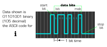
Let's walk through the transmission of one byte of data. Per figure 1, the serial line starts off low, in its idle or stop-bit state. It can stay in this state forever--the receiving device understands this to mean that no data is available. When there is data to send, the following sequence of events occurs (from the perspective of the sender):
- The sender outputs a high level for one bit time1--the start bit
- At intervals of 1 bit time, the sender outputs the data bits in inverted form (i.e., with a high voltage meaning "0" and a low or negative voltage meaning "1"). The data bits are sent in order from least-significant bit (lsb)2 to most-significant bit (msb)2.
- After the final data bit, the msb, is sent, the sender returns to the low/stop-bit state for at least one bit time. After this, it may send another byte or remain idle.
Notes:
1. A bit time is defined as 1/bps. For example, at 9600 bps the bit
time is 1/9600 = 104 microseconds.
2. The "significance" of a bit or digit is its relative value. When
we write numbers, the most-significant bit/digit is the one
furthest to the left.
Figure 2 shows how this might look on an oscilloscope.
 |
| Figure 2. Serial data is framed by a start bit and a stop bit. |
It should be obvious that timing is very important to proper reception of this kind of serial data (called asynchronous serial data because there's no separate clock signal to help the receiver sort out the bits--just the relative timing of the start and stop bits). Under ideal conditions, no more than a few percent timing error is tolerable. For consistently reliable communication, the goal should be to keep timing errors to less than one percent.
Tips to Remember
Here are a couple of practical hints regarding serial timing:
- If the received data is totally garbled, then the sender and receiver are probably set to different baud rates. If there are just occasional errors, then the baud rates may be slightly off--see next item.
- In general, if the sender is a PC or has a hardware UART1, its baud-rate timing can be considered accurate. If the sender is a microcontroller that is bit-banging2 the serial output, it is worth investigating as a source of timing problems.
- A PC serial output makes a good reference for accurate serial output timing, because its timing is likely to be right on the money. However, a PC's serial input is usually exceptionally tolerant of timing errors, so it is not such a good test of the quality of another device's serial output. Just because a PC can receive a given sender correctly doesn't mean that sender's timing is good! Other devices under other conditions may still have problems if the timing is sloppy. See the scope test below.
- Some senders allow you to configure variable stop-bit timing (e.g., 1, 1.5, 2 or more stop bits). All this amounts to is a little additional time between transmitted bytes. Higher than necessary stop-bit times never cause reception problems. For example, if the receiver specifies 1 stop bit and the sender is set for 2 stop bits, no problem. In fact, if the sender has sloppy serial timing, setting a higher stop-bit value can sometimes improve reception.
Notes:
1. UART (universal asynchronous receive/transmit chip), a hardware
device for serial communication.
2. Bit-banging means generating serial output in software as
opposed to with a hardware UART. Timing accuracy of bit-bang output
is only as good as the program that generates it, the accuracy of
the system clock, and in interrupt-equipped systems, the degree to
which other interrupts affect timing. Some compilers generate truly
bad bit-bang serial timing, based on the assumption that the
receiver is always going to be a PC (with its generous error
tolerance).
Testing Serial Timing
If you have a decent oscilloscope, you can easily perform a
sanity check on serial timing. Set up the computer that you wish to
test to continuously transmit the space character
(ASCII 32; 0x20 hex). View the output on the oscilloscope
(triggered on the rising edge). You'll see a rectangle with a notch
near the middle. Adjust the scope so that you can accurately
measure the time-width of the notch. It should be exactly
one-bit-time wide. If it's off by more than a percent, that's a
potential problem.
| Baud Rate | Bit Time (us) | Max Error (us) |
|---|---|---|
| 1200 | 833.33 | 8 |
| 2400 | 416.67 | 4 |
| 4800 | 208.33 | 2 |
| 9600 | 104.17 | 1 |
Note: Some will refute this 1% rule as excessively strict, and cite anecdotal evidence of systems with worse timing that work just fine. After all, errors in asynchronous communication are not inevitable until the timing error reaches 5%. (Really, that number should immediately be cut to 2.5% so that sender and receiver get equal shares of the error budget.) The 1% rule just says that if your serial timing is within 1%, you won't have problems; if it's greater, you may.
Timing accuracy of 1% is pretty easy to achieve in a properly designed system, so strict or not, it's a reasonable guideline.

