BPK-000 Hardware Reference
This page describes the LCD Serial Backpack, installation, specs, schematic and warranty. For information on sending data and instructions to the Backpack please see the programmer's reference.
Table of Contents
- Hardware
- Cautions/Warranty
- Compatibility and Installation
- Connection/Configuration
- Circuit/OEM Integration
Cautions and Warranty
- Do not exceed the maximum supply voltage of 5.3Vdc.
- Always ensure that supply polarity is correct.
- Protect the unit from electrostatic discharge (ESD).
- Do not disassemble, drill or modify in any way.
Seetron warrants this product against defects in materials and workmanship for a period of 90 days. If you discover a defect, we will, at our option, repair, replace, or refund the purchase price. Return the product with a description of the problem. We will return your product or its replacement via standard shipping. Expedited shipping is available at the customer's expense. Note: Violating the usage guidelines above, or attempting to repair or modify the module or the serial interface, voids this warranty.
Compatibility and Installation
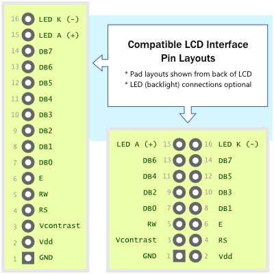
BPK-000 works with standard character LCD modules having the following characteristics:
- Controller type: HD44780, KS0066 or ST7066 families
- No more than 80 screen characters total (i.e., 1-, 2- and 4-line models up to 4x20 OK; 4x40 incompatible)
- Standard 1- or 2-row interface pinout (examples shown below)
- Non-negative contrast voltage (Vo in spec sheet)
- LED backlight (if present) connected separate from logic supply via pins 15 and 16.
Note that LCD-workalike VFDs and OLEDs are not compatible with BPK-000 due to their high current draw. If you have a question about a particular LCD's compatibility, please contact tech@seetron.com. Be sure to provide a link to the LCD's documentation.

Prepping the LCD and Installing the Backpack
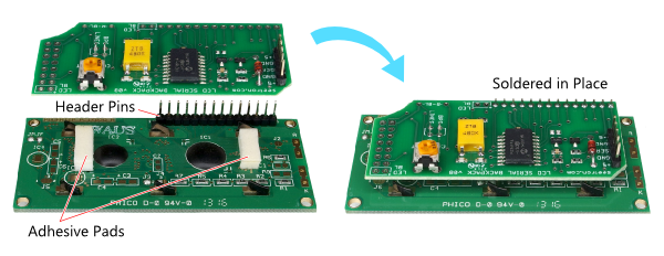
Solder header pins to the LCD's interface pads with the long part pointing straight backward. Apply small pieces of foam adhesive to component-free flat spots on the LCD pcb. Install the BPK-000 down onto the header pins, with pin 1 of the BPK (square pad) going to pin 1 of the header. If the LCD does not have a backlight, pins 15 and 16 will be unused.

Example Mounting to LCD with One-row Header.

Example Mounting to LCD with Two-row Header.
Connection/Configuration
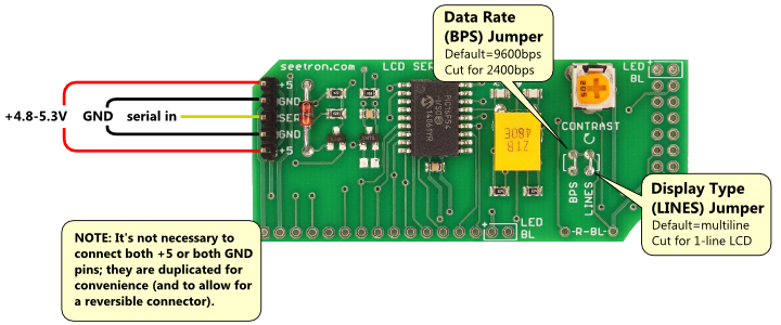
BPK-000 requires three connections: 5Vdc (regulated), serial input (2400 or 9600 bps, N81) and ground (connected to both power and the computer/controller).

BPK-000 Basic Connections.
Serial Input
BPK-000 accepts inverted serial input, such as the output of an *RS-232 port. The direct output of a UART is noninverted; it is not compatible unless inverted (NOT gate). In some cases, workarounds exist to avoid the additional component:
- Arduino v1.0+ SoftwareSerial supports inverted output:
SoftwareSerial(rxPin, txPin, 1);(where 1 sets inverted output). - Basic Stamp SEROUT instructions accept a parameter that inverts the output in software.
- PIC microcontrollers with the "enhanced" USART (EUSART) can be configured for inverted output by setting the SCKP bit of the BAUDCON register during USART initialization.
*RS-232 serial signals often use ±10V signals. These voltages will not harm the BPK-000, which has a protective circuit on its serial input.
LED Backlight Hookup
Pins 15 and 16 of the LCD interface connector are wired for common LED backlights. They are wired as follows:
- Pin 15: Connected to +5Vdc (separate from LCD Vdd)
- Pin 16: Connected via R-BL to Ground
To light the backlight, install an appropriate resistor (1/8 to 1/4-watt through-hole) at the pads R-BL. The value of this resistor must be calculated to limit the backlight current; typical resistor values range from *0 to 100 ohms. (*Use 0 only for LCD modules with a built-in current-limiting resistor.) For assistance selecting a resistor, contact tech@seetron.com, making sure to include a link to documentation for the target LCD.
Test Mode and Contrast Adjustment
You can check your Backpack installation with a 5Vdc power supply (no serial connection required). Turn the BPK Contrast control fully clockwise and make the following connections (with the power supply turned off):
- BPK +5 to power supply +5Vdc
- BPK GND to power supply Ground
- BPK SER to power supply +5Vdc
When you turn on the power, a test message should appear on the LCD.

BPK-000 Test Message
(version refers to BPK firmware; 4.00 is current).
If the message fails to appear, make sure that the contrast control is fully clockwise (as shown in the 'Basic Connections' photo above) and that all connections between the BPK-000 and the LCD are properly soldered. If the screen is too dark, turn Contrast counter-clockwise until the screen is readable.
If the screen appears active (light-colored 'ghost' pixels appear at power on) but the test message does not appear, the SER input of the BPK-000 may not be solidly connected to +5Vdc. (The test message triggers off several hundred milliseconds of continuous logic high on SER throughout startup. If the logic high is interrupted, the test message is cancelled.)
Circuit and OEM Integration
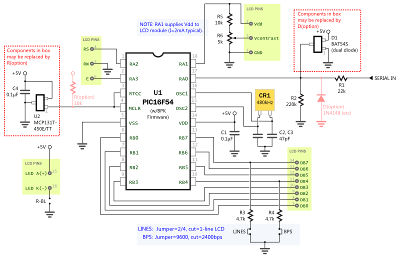
Seetron sells the PIC16F54 controller chip programmed with BPK-000 firmware for integration into custom designs. Circuit layout is relatively non-critical and only a few support components are required. Some components may be substituted or omitted completely (marked 'option' in the diagram below). Questions about applications, modifications or component sourcing: contact tech@seetron.com.

BPK-000 Schematic (click for PDF version).

