
GLO-416 Hardware Reference
This page describes the GLO-416's hardware, hookup, configuration and specifications. For information on sending data and instructions to the display please see the programmer's reference.
Table of Contents
Cautions and Warranty
Handling, Usage and Operating Precautions
- Do not exceed the maximum supply voltage of 5.3Vdc.
- Always ensure that supply polarity is correct.
- If the screen requires cleaning, use low-tack tape to remove dust.
- Do not wipe or scrub the screen; it is easily scratched.
- In a permanent installation, mount the display behind a transparent window.
- Protect the unit from electrostatic discharge (ESD).
- Do not subject the display to sharp impact or mechanical pressure.
- Do not disassemble, drill or modify the unit in any way.
- Do not allow solvents, cleaners, or water to come into contact with the screen.
- Do not operate when wet or under conditions of condensing humidity (dew).
- To avoid burn-in, do not display static messages. Vary screen content, reduce brightness, or employ other 'screen saver' methods.
Seetron warrants this product against defects in materials and workmanship for a period of 90 days. If you discover a defect, we will, at our option, repair, replace, or refund the purchase price. Return the product with a description of the problem. We will return your product or its replacement via standard shipping. Expedited shipping is available at the customer's expense. Note: Violating the usage guidelines above, or attempting to repair or modify the module or the serial interface, voids this warranty.
Connection/Configuration
Hooking up the GLO-416 requires three connections: +4.8 to 5Vdc (regulated), serial input (9600 bps, N81) and ground (connected to both power and the computer/controller).
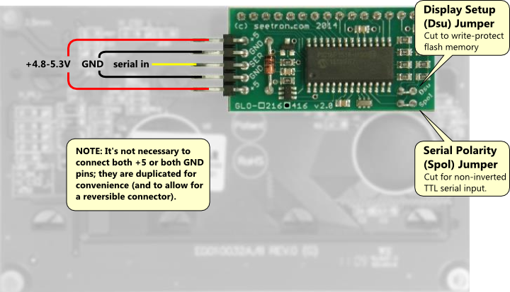
GLO-416 Serial Interface Board.
Configuration Jumpers
There are two configuration jumpers on the GLO-416 serial interface:
- Dsu (Display Setup): Uncut= EEPROM writes allowed; Cut= EEPROM write-protected
- Spol (Serial Polarity): Uncut=Inverted TTL or RS-232 serial; Cut= Non-inverted TTL (UART-direct) serial
Dsu prevents a runaway program or other error from altering EEPROM contents. This jumper should be cut after the display is configured with an appropriate startup screen and/or default custom characters.
Spol sets the polarity of the serial input. It should be left uncut if GLO is to be used with an RS-232 port (PC com port, or USB adapter with a 9-pin D connector), or in a microcontroller application that outputs inverted serial. That would include applications that previously worked with older Seetron serial LCDs, such as BPI, BPK, BPP, ILM, and VFD-series devices.
Spol should be cut if the GLO is to be connected directly to a UART-type device, or microcontroller that acts like one, outputting non-inverted TTL serial. This includes inexpensive USB serial adapters that connect via breadboard pins, and many single-board computers (e.g., Arduino) whose documentation states that their serial output is not RS-232 compatible.
Serial Input Electrical Chacteristics
The GLO-416 is directly compatible with both RS-232 and UART-direct serial hookups. This information is provided for the benefit of users who may be interfacing the display to low-voltage or nonstandard logic devices.
The serial input of the GLO-416, shown below, uses an XNOR gate with Schmitt-trigger characteristics. Under logic control (marked Spol Out), the gate is set as inverting or noninverting as needed to deliver the correct data polarity to the controller's UART input. Spol Out also ensures that the serial input is lightly pulled to the idle state (low for inverted input; high for noninverted) to ensure that the input doesn't float when disconnected.
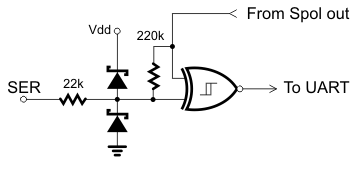
These features reject noise that might otherwise show up as garbage characters on the screen. They also complicate the question of the serial-input logic threshold, since this will depend on the Spol setting and the edge (rising or falling) of the input signal. In the table, 'Transition' refers to the direction of change on the serial input (output of the device driving the GLO-416). The idle-to-start-bit transitions are highlighted.
| Spol | Input Type | Transition | Vthreshold |
|---|---|---|---|
| Uncut | Inverted | Low-High↑ | 3.0V |
| High-Low↓ | 2.0V | ||
| Cut | Noninverted | Low-High↑ | 2.6V |
| High-Low↓ | 1.6V |
Dimensions (in mm)
Total depth (front of screen to highest point on pcb) is 16mm.
| A | y offset edge to hole center (top & bottom) | 2.50 |
|---|---|---|
| B | y pcb height | 60.00 |
| C | y hole spacing | 55.00 |
| D | y screen opening | 25.20 |
| E1 | y character height (4-line fonts) | 4.20 |
| E2 | y character height (2-line fonts) | 8.40 |
| E3 | y character height (1-line fonts) | 16.8 |
| E4 | y character height (7-seg*) | 19.1 |
| F1 | x character width (16-character fonts) | 2.95 |
| F2 | x character width (8-character fonts) | 5.90 |
| F3 | x character width (4-character fonts) | 11.8 |
| G | x offset pcb edge to hole center | 2.50 |
| H | x screen frame | 94.00 |
| I | x screen opening | 77.00 |
| J | x hole spacing | 93.00 |
| K | x pcb width | 98.00 |
| L | y frame height | 32.00 |
| - | mounting hole diameter | 2.50 |
| - | screen frame depth | 4.70 |
| *Large numbers (1x4 and 1x8) can be displayed in 7-segment style, maximizing their overall size (32 pixels tall). Optionally, they can be displayed in the same proportions as large text, 28 pixels tall. | ||
Mounting
As mentioned in "Cautions" above, GLO-416 must be mounted behind a transparent window in any permanent installation. If it is not, the screen will be vulnerable to damage from users' fingers (e.g., electrostatic discharge or mechanical stress), moisture, dirt, mechanical damage, etc. Damage of this kind is not covered by warranty.
An inexpensive mounting kit is available for these devices (PN: BEZ-416G), but any transparent barrier will suffice.
Specifications
| Power Requirements | 4.8 to 5.3Vdc at 50mA (60mA max) |
|---|---|
| Serial Input (electrical) | RS-232 (±15V OK), UART, TTL |
| Serial Input (logic/data) | Inverted or noninverted, 9600—38,400bps |
| User Connector | 5-pin header, 0.025in. posts on 0.10in. centers |
| Connector Pinout | +5V Gnd Serial Gnd +5V |
| Operating Temp. | -40° to +80° C (-40° to +176°F) |
| Display Type | Organic LED (OLED), yellow pixels on black bkgd |
| Contrast Ratio | 2000:1 |
| Font Sizes | 5x7 pixels, 4.2 to 19.1mm (0.16 to 0.75 in.) height |
| Overall Size (wxhxd) | 98x60x16mm (3.86x2.36x0.63in.) |